
Solar plant AC grounding and ground grid design: IEEE 80 field guide
EPRI grounding incident research and OSHA 1910.269 fatality investigation records document multiple electrocutions at utility substations caused by unsafe step and touch voltages during phase-to-ground faults. IEEE 80-2013 exists precisely to prevent that outcome. Solid solar plant grounding design IEEE 80 practice keeps step and touch voltages below the fibrillation threshold when a ground fault dumps thousands of amps into the earth around your inverter pads, main power transformer, and collector substation. This field guide walks the design and verification workflow used on modern utility-scale plants.
Solar plant grounding design IEEE 80: step and touch potential limits
Solar plant grounding design IEEE 80 methodology begins with the two voltages that can kill a worker: step potential (the voltage between two feet 1 metre apart) and touch potential (the voltage between a hand and a foot 1 metre from a grounded structure). IEEE 80-2013 sets tolerable limits with the Dalziel electrocution formulas, adjusted for body weight, fault clearing time, and any surface layer such as crushed stone. The four Dalziel formula inputs are body weight (50 or 70 kg), surface layer resistivity in ohm-metres, surface layer depth in millimetres, and fault clearing time in seconds. For a 50 kg worker, 0.5 second clearing, and a 3,000 Ω·m rock surface layer, the tolerable step voltage exceeds 2,000 V while touch tolerance sits near 700 V. Every square metre of your solar substation must stay under that touch limit during the maximum available ground fault. The IEEE 80-2013 published guide carries the full formulas and design workflow.
Solar plants introduce complications transmission substations do not face. Inverter pads scatter across hundreds of acres, tied together only by underground medium-voltage cable. The collector substation still needs a compact high-current ground grid, but every pad, tracker row, and control shelter also needs a bond to earth to keep touch potentials low during faults far from the main power transformer. Ignore the DC field grounding and you often produce a passing fall-of-potential result at the substation while leaving inverter enclosures at unsafe touch potential during grid-side faults. OSHA 29 CFR 1910.269 makes those controls mandatory at every US utility-scale plant.
There is a full breakdown of this topic in Solar farm lightning protection IEC 62305 and SPD field guide.
For a closer look at this, see Solar farm arc flash analysis NFPA 70E: IEEE 1584 and PPE guide.
For a closer look at this, see Solar plant SCADA system modernization: a utility upgrade roadmap.
For a closer look at this, see IEEE 1547 solar interconnection: voltage ride-through guide.
For a closer look at this, see BESS SCADA Integration for Utility-Scale Solar Plants: A Field Guide.
For a closer look at this, see Solar tracker SCADA integration: backtracking and tag map design.
For a closer look at this, see Solar string IV curve tracing: field methods for degradation detection.
For a closer look at this, see Solar drone thermal inspection: utility-scale hotspot field guide.
For a closer look at this, see IEEE 1588 PTP Time Sync for Solar SCADA: GPS Clock Field Guide.
For a closer look at this, see Solar Curtailment and AGC in Utility-Scale Solar Plant Operations.
For a closer look at this, see Solar Farm Revenue Metering: ANSI C12.20 Accuracy Field Guide.
For a closer look at this, see Solar Power Plant Controller: SCADA Integration, Setpoints, Limits.
For a closer look at this, see How solar SCADA reduces unplanned downtime at utility-scale plants.
For a closer look at this, see Solar plant frequency response: FFR and synthetic inertia guide.
There is a full breakdown of this topic in Solar plant reactive power control: inverter VAR dispatch guide.
For a closer look at this, see Solar plant transformer DGA: dissolved gas analysis field guide.
Soil resistivity testing before solar plant grounding design IEEE 80 modeling
You cannot model a ground grid without measuring the ground. IEEE 81-2012 specifies the four-electrode Wenner array as the reference method: four evenly spaced electrodes driven into the earth, current injected across the outer pair, voltage read across the inner pair. Vary spacing from 1 metre to 30 metres and you build the two-layer resistivity model that captures both topsoil and the deeper substrate carrying most of the fault current away from your grid.
For solar plant grounding design IEEE 80 workflows we run a minimum of three orthogonal traverses across the collector substation footprint, plus one traverse per 25 MW of DC field, per IEEE 81-2012 guidance. Winter and summer readings often differ by a factor of two on the same site because frozen or dry soil resistivity climbs sharply. If you built the grid model on August resistivity data, verify with a February retest before signing off on the fall-of-potential result. The NREL 2021 utility-scale PV benchmark flagged winter grounding issues as a recurring commissioning defect.
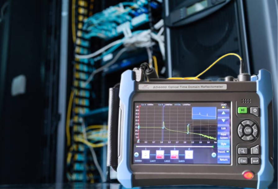
We cover the details separately in Fiber optic installation solar farm: OTDR testing field guide.
Sizing the substation grid to solar plant grounding design IEEE 80 fault criteria
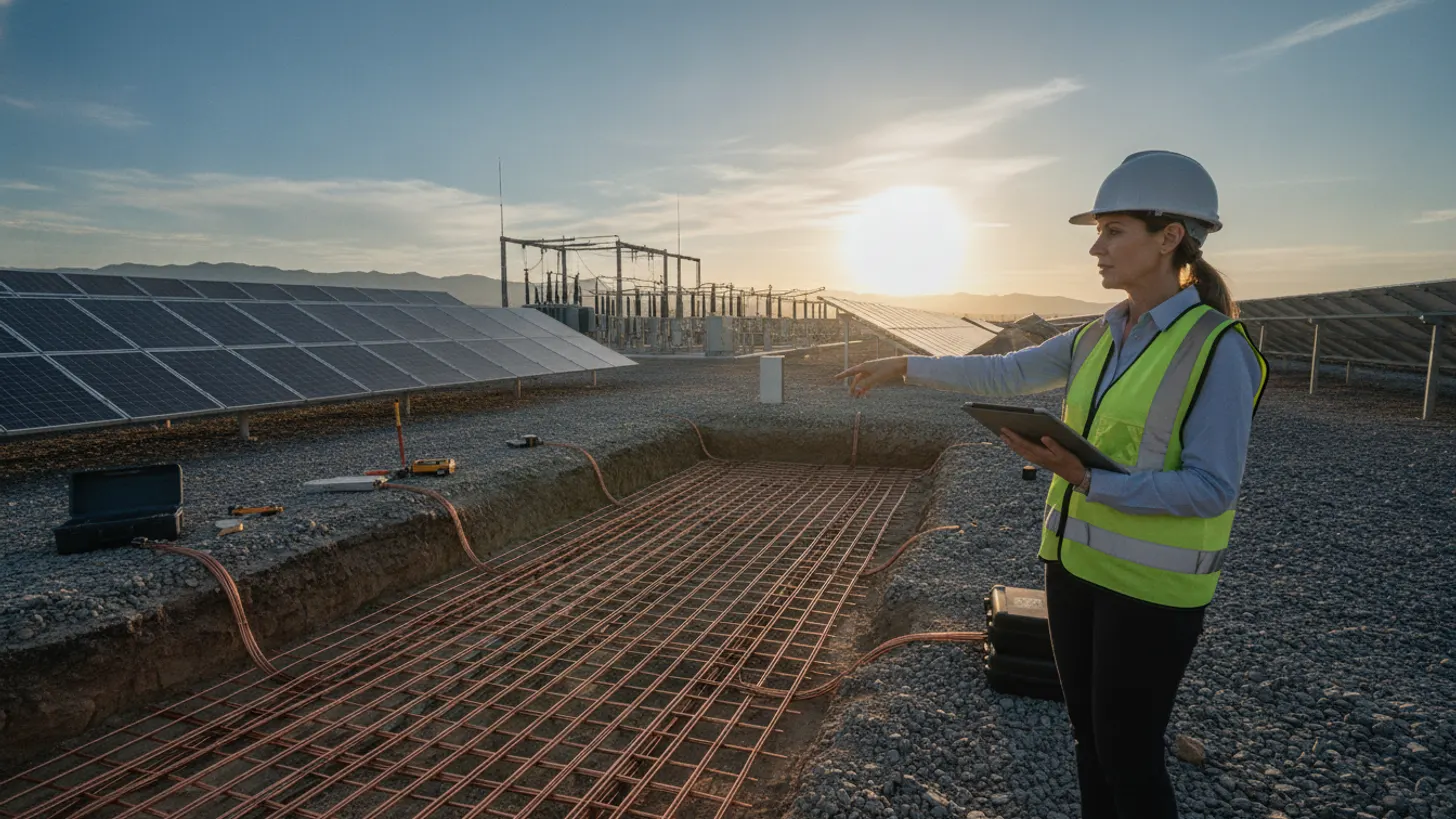
Ground grid sizing under solar plant grounding design IEEE 80 rules is an iterative loop between conductor cross-section, mesh spacing, ground rod count, and the resulting grid resistance, mesh voltage, and step voltage. Start with the available fault current at the collector bus (from the transmission utility POI study), the fault clearing time from your relay coordination study, and the two-layer soil model. Copper conductor size follows the Sverak equation in IEEE 80 Section 11.4, sized for the fusing temperature at that clearing time. For 20 kA and 0.5 s, 4/0 AWG copper is the common answer.
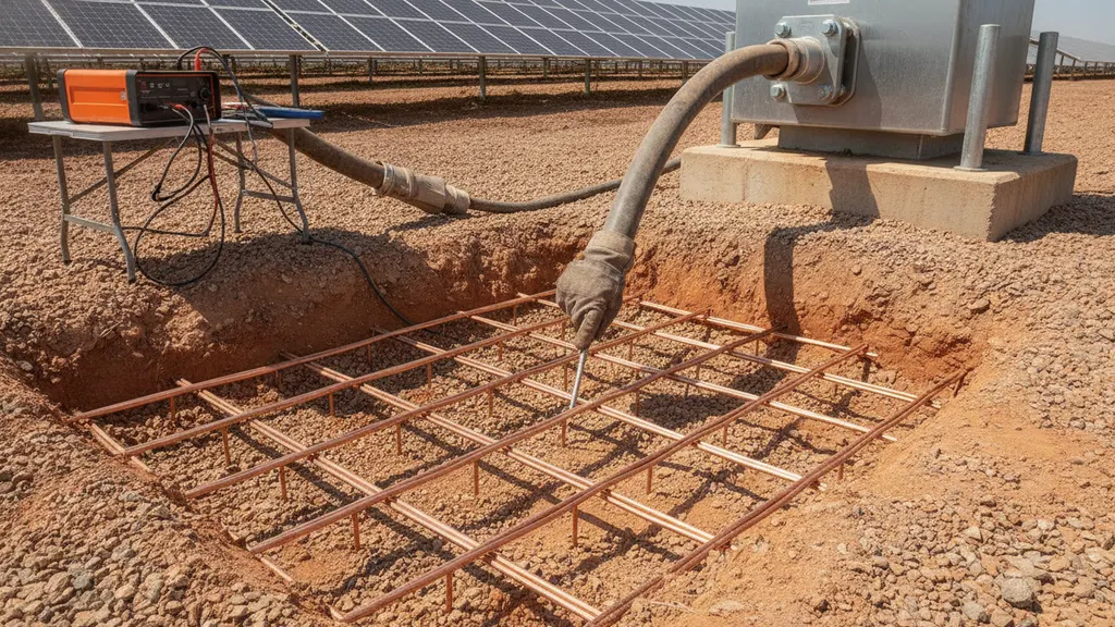
Mesh spacing sets the touch voltage. Tighter spacing lowers touch voltage but drives copper cost. Most solar collector substations converge on 3 to 4 metre spacing after two or three modeling passes in CDEGS, ETAP GroundMat, or WinIGS. Add ground rods at the perimeter and beneath the main power transformer neutral to pull grid resistance below 1 Ω on typical sites. The design pass check: mesh voltage at least 15 percent below tolerable touch, step voltage at least 15 percent below tolerable step at every location.
The dashed IEEE 80 tolerable touch line is the pass/fail boundary for a 50 kg worker under 0.5 s clearing on a crushed-stone surface. A 5 metre mesh fails; a 4 metre mesh clears with margin. The EPRI grounding research briefs catalog similar case data from US collector substations.
For a closer look at this, see DC Ground Fault Detection in Utility-Scale Solar: NEC 690.5 Field Guide.
For a closer look at this, see Solar substation transformer differential protection: IEEE C37.91 guide.
Verifying solar plant grounding design IEEE 80 performance at energization
Modeling gets you a design; measurement confirms it. At energization every solar plant grounding design IEEE 80 hand-off must include three field tests: fall-of-potential for grid resistance, a step-touch potential survey at operator locations, and continuity checks on every bond from a grounded structure back to the grid. Fall-of-potential (IEEE 81 Section 8) injects a known current between the grid under test and a remote current probe, then walks a voltage probe out along the axis to plot a resistance profile. The characteristic 61.8 percent flat spot on that profile is the true grid resistance.
Step-touch surveys use a variable-load resistor bank across a hand-and-foot electrode arrangement to measure the actual voltage a worker would experience at each operator location during an imposed test current, scaled to the maximum fault. Any location above the tolerable touch envelope gets remediated with additional bonding, a wider crushed-stone surface, or an equipotential mat. See our solar SCADA commissioning witness pack guide for the paperwork the utility expects to sign at these results.
AC substation vs DC bonding: how NEC 690 diverges from IEEE 80
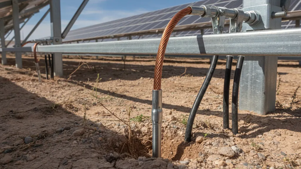
Utility-scale sites live under two grounding codes. Solar plant grounding design IEEE 80 methodology covers the AC collector substation and its 34.5 kV or 12.47 kV bus under the utility ownership boundary. Everything on the DC side (module frames, rack rails, combiner boxes, inverter enclosures, tracker piers) follows NEC Article 690 and the equipment grounding conductor rules of NEC Article 250. The two systems must be bonded together per NEC 250.50 or you create hazardous voltage differentials during a fault.
| Dimension | IEEE 80 (AC substation) | NEC Art. 690 / 250 (DC field) |
|---|---|---|
| Scope | AC collector substation earthing: 34.5 kV or 12.47 kV collector bus within the utility ownership boundary | DC arrays, string combiners, inverter enclosures, tracker frames, and racking rails throughout the solar field |
| Fault scenario | High-current ground faults (15-30 kA) producing step and touch voltage hazards at operator-accessible locations | DC ground fault arcing and equipment bonding to limit touch voltage on non-current-carrying metal parts |
| Conductor sizing method | Sverak equation per IEEE 80 Section 11.4, sized for thermal withstand at the specified fault clearing time | Equipment grounding conductor tables per NEC 250.122 and 690.45, sized for the overcurrent device rating |
| Primary test standard | IEEE 81-2012 fall-of-potential and step-touch survey at energization | Continuity bond verification per NEC 690.31; insulation resistance per IEC 62446-1 |
| OSHA citation | 29 CFR 1910.269(l)(6): step and touch voltage engineering controls at power generation facilities | 29 CFR 1926.416 during construction; NFPA 70E for DC arc flash at inverter terminals |
| Integration point | Ground grid serves as the reference earth for the entire plant | DC equipment grounding conductors must bond back to the IEEE 80 ground grid per NEC 250.50 |
Common failures we catch at commissioning: tracker piers used as the sole earth path (they are not, per DOE Systems Integration Office guidance); module frame bonding jumpers omitted at every fourth row where cross-tie hardware differs; inverter pad grounds bonded only to pad rebar without a separate grounding electrode conductor back to the substation grid. See our DC ground fault detection field guide and arc flash analysis workflow for adjacent DC-side procedures. Coordinate the two grounding worlds early or the utility will refuse the fall-of-potential result at energization.
Frequently asked questions
What tolerable step and touch potential does IEEE 80-2013 use as the design target?
IEEE 80-2013 derives tolerable step and touch voltages from the Dalziel body current equation, sized to keep a 50 kg worker below the ventricular fibrillation threshold for the duration of the fault. The Dalziel constant for a 50 kg body is 0.116, established in published electrocution studies and reproduced in IEEE 80-2013 Section 7. Common design values on a solar substation with 0.5 second clearing and a 100 mm crushed-stone surface layer land near 700 V tolerable touch and 2,200 V tolerable step per Section 8. IEEE 80 Table 7 provides derating factors that lower the allowable voltage when the surface layer resistivity falls below design assumptions; for 100 mm of 3,000 Ω·m crushed stone, that derating factor exceeds 5, which is why surface material selection matters as much as grid geometry. Some utilities require a 70 kg body weight, but the 50 kg case is the conservative default per the IEEE 80-2013 published guide.
How do you run a Wenner soil resistivity survey before ground grid design?
Drive four electrodes into the earth in a straight line with equal spacing, inject a low-frequency current across the outer pair, and read the resulting voltage across the inner pair. Repeat at spacings from about 1 metre to at least the diagonal of the planned ground grid, usually 30 to 100 metres on solar substations. Convert readings to apparent resistivity with the Wenner formula, then curve-fit to a two-layer soil model in your grounding software. IEEE 81-2012 documents the array geometry, and the NREL utility-scale commissioning benchmark flags winter retests as routine.
What conductor size and mesh spacing does solar plant grounding design IEEE 80 require for a typical substation?
A collector substation carrying 15 to 30 kA of available fault current at 0.5 second clearing usually settles on 4/0 AWG bare copper for the grid conductor, sized per the Sverak equation in IEEE 80 Section 11. Mesh spacing typically converges on 3 to 4 metres after two or three model iterations, with additional ground rods at the perimeter and beneath the main power transformer neutral. Design targets: grid resistance below 1 ohm, mesh voltage at least 15 percent below the IEEE 80 tolerable touch voltage, and step voltage below the tolerable step envelope at every operator location.
How is fall-of-potential testing conducted after energization?
Inject a known test current between the completed grid and a remote current probe placed at least five times the grid diagonal away. Walk a voltage probe out along the same axis and record the resistance at each position. Plot the resistance versus distance curve: the flat portion near 61.8 percent of the distance to the current probe is the true grid resistance. If the measured value lands within 20 percent of the model number the grid passes per IEEE 81-2012 Section 8. Larger deviations mean soil parameters were wrong or a bond has been missed.
How do NEC 690 DC grounding rules differ from IEEE 80 AC substation grounding?
IEEE 80 is a safety envelope calculation for AC substation earthing under high-current ground faults, focused on step and touch potentials. NEC Article 690 governs the DC side of the solar plant (arrays, combiners, inverters) and requires equipment grounding conductors that bond every non-current-carrying metal part back to a system grounding electrode. The two worlds must be bonded together at the inverter or at the medium-voltage transformer per NEC 250.50, or transient voltage differences during a fault will inject dangerous potentials into the DC field, per DOE Systems Integration Office guidance.
Does OSHA require documented grounding safety records at utility-scale solar?
Yes. OSHA 29 CFR 1910.269 applies to employees engaged in power generation, transmission, and distribution work, which explicitly includes utility-scale solar plants once interconnected to the transmission grid. The controlling provision is 29 CFR 1910.269(l)(6), which requires employers to determine voltage exposure limits at generating and transmission installations and apply engineering controls sufficient to keep workers within those limits. Required documentation includes the grounding study report, soil resistivity survey data, fall-of-potential test records showing the 61.8 percent flat-spot resistance, step-touch survey results at every operator location, and bond continuity check logs. Fall-of-potential and step-touch survey reports from energization are the evidence utility owners retain to prove compliance during OSHA 1910.269 audits.