
Solar plant frequency response: FFR and synthetic inertia guide
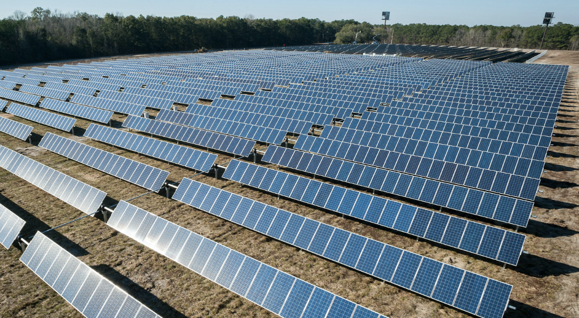
FERC Order 842 requires every new large solar generator above 20 MW to demonstrate primary frequency response capability before it can accept commercial dispatch, with a governor droop no wider than 5% and a dead-band no wider than 0.036 Hz. Solar plant frequency response is now a first-day interconnection deliverable, not an optional grid service, and inverter-based resources paired with BESS assets can meet the target inside 500 milliseconds. This field guide walks through the settings, standards, and commissioning tests that pass NERC and interconnection review.
What FERC Order 842 requires for new solar generators
FERC Order 842, issued in February 2018, extended primary frequency response obligations to every new generating facility seeking interconnection above 20 MW, closing a decades-old carve-out that had exempted many inverter-based resources. Solar plant frequency response capability is now written into the Large Generator Interconnection Agreement (LGIA) as a signed technical commitment.
The rule sets a governor droop no wider than 5% and a dead-band no wider than 0.036 Hz, matching the technical envelope conventional generators have observed under the older Order 693 framework. New solar generators must demonstrate this capability during AC injection studies before the Federal Energy Regulatory Commission will approve the LGIA. The rule does not extend retroactively to legacy plants, so most retrofit projects take on frequency response after a repowering event or an owner-driven grid-service upgrade.
Order 842 also codifies the difference between primary frequency response, sustained through the settlement window, and the sub-second fast frequency response that inverter-based resources can supply. Both live in the same LGIA compliance test package. For a deeper walkthrough of the LGIA voltage envelope, see our field guide on IEEE 1547 interconnection voltage ride-through.
Configuring power plant controller settings for solar plant frequency response
At 5% droop, curtailing the plant 3.3% below its available power ceiling delivers the full solar plant frequency response mandate for a 0.1 Hz deviation, and the power plant controller (PPC) enforces that calculation fleet-wide in under 200 milliseconds from the moment a class 1 phasor measurement unit detects the excursion. That latency budget drives every PPC configuration choice: dead-band edge, droop slope, ramp-rate ceiling, and the return-to-service delay after each event.
The active power correction follows the droop equation ΔP/P_max = -Δf / (droop × f_nom). At 5% droop and 60 Hz nominal, a 0.1 Hz drop below the 0.036 Hz dead-band commands a 3.33% headroom lift on every inverter. That headroom has to exist before the event, so operators curtail the plant against its unclipped setpoint by a matching percentage. The National Renewable Energy Laboratory published reference droop curves and PPC tuning notes in its 2020 report on primary frequency response from inverter-based resources.
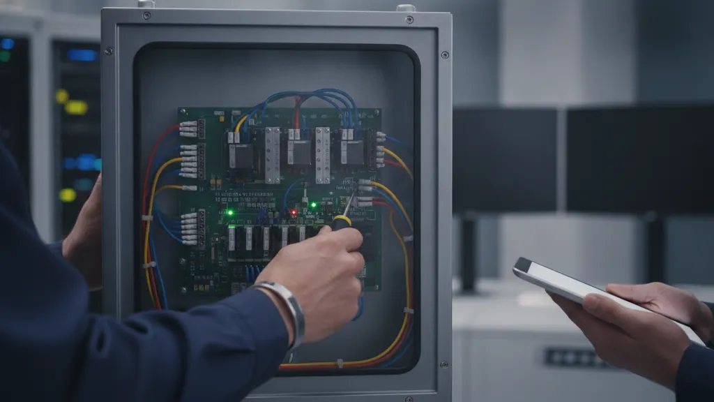
Real installations also expose ramp-rate limits, over-frequency curtailment slopes, and a return-to-service delay after each response event. Best practice is to log the raw frequency signal, the calculated dead-band exit, the commanded setpoint, and the measured plant output on the same time base at 100 ms resolution so the compliance record survives a NERC audit. Time base accuracy comes from IEEE 1588 PTP time sync at the SCADA layer.
For a closer look at this, see Solar Power Plant Controller: SCADA Integration, Setpoints, Limits.
For a closer look at this, see How solar SCADA reduces unplanned downtime at utility-scale plants.
For a closer look at this, see Solar Curtailment and AGC in Utility-Scale Solar Plant Operations.
For a closer look at this, see Solar plant SCADA system modernization: a utility upgrade roadmap.
For a closer look at this, see Solar plant AC grounding and ground grid design: IEEE 80 field guide.
For a closer look at this, see Solar plant transformer DGA: dissolved gas analysis field guide.
For a closer look at this, see Solar plant reactive power control: inverter VAR dispatch guide.
Fast frequency response and synthetic inertia from a co-located BESS
Fast frequency response delivers active power inside 500 ms of a frequency event, compared with the 10 to 30 second window of synchronous governor action, per joint EPRI and NERC studies on inverter-based resource integration. That gap is what makes a co-located BESS the practical path to solar plant frequency response above the primary layer.
A pure PV array at full irradiance cannot deliver upward FFR because it has no stored energy above its instantaneous output. Adding a BESS gives the plant a bidirectional headroom pool and lets the PPC emulate synthetic inertia by pushing active power proportional to the rate of change of frequency (dP/dt gain). The synthetic inertia loop runs alongside the droop loop with a lockout so the two do not fight each other during a nadir event.
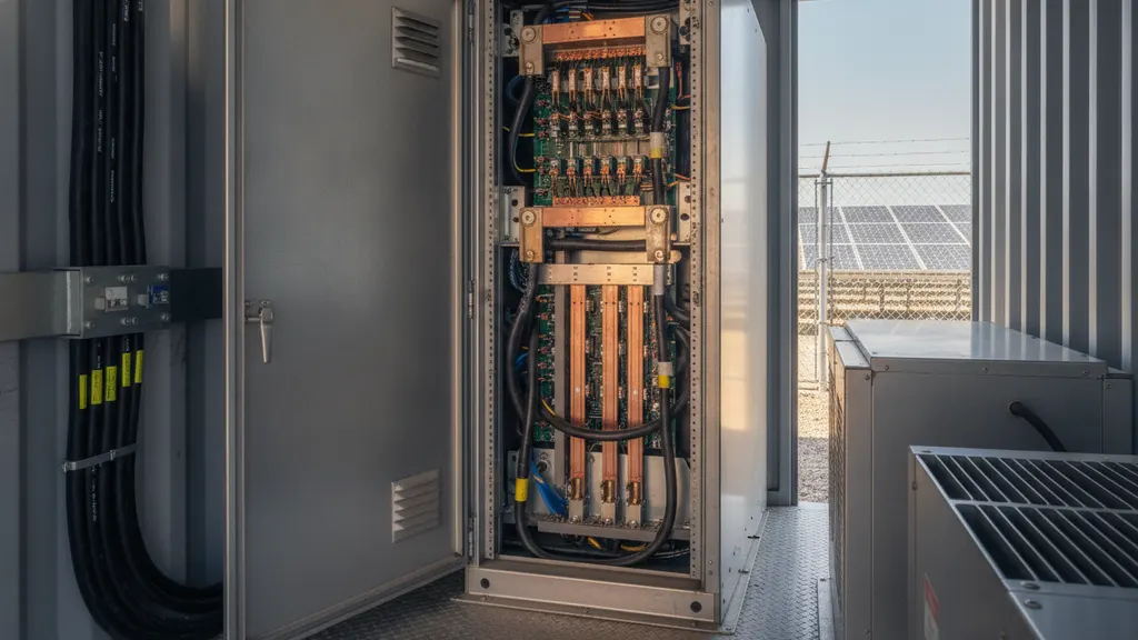
Battery sizing for grid service follows a different rule than energy arbitrage. A 1 MW / 15 minute BESS can carry FFR duty for a solar plant many multiples its size because each event lasts only a few seconds. Site-level tuning for BESS SCADA integration is covered in our BESS SCADA integration field guide.
| Service | Response window | Duration | Typical source |
|---|---|---|---|
| Synthetic inertia | Under 200 ms | Under 5 s | BESS with dP/dt gain |
| Fast frequency response | 200 to 500 ms | 5 to 30 s | Inverter fleet or BESS |
| Primary frequency response | 2 to 30 s | Up to 5 min | PPC droop on curtailed PV |
| Regulation (AGC) | 2 to 5 min | Continuous | PPC setpoint from ISO |
NERC BAL-003-2 obligations and solar plant frequency response reporting
NERC BAL-003-2 assigns a frequency response obligation (FRO) to each balancing authority, expressed in MW per 0.1 Hz of frequency deviation. The FRO is calculated annually from the prior year interconnection performance data under the NERC frequency response sharing methodology, per NERC. Solar plant frequency response contributions feed directly into that balancing-authority number.
The measurement window sits between the start of the disturbance and the point 20 to 52 seconds later, called the B value point. NERC calculates response by dividing the balancing authority active power delta by the interconnection frequency delta over the same interval. Each balancing authority reports its ten worst events per year and must show a median response at or above the FRO.
Balancing authorities that miss the FRO for two consecutive years face a compliance escalation. Utility-scale solar operators are usually not the reporting entity, but their commissioning report gets pulled during the review, which is why the PPC data recorder needs to hold at least two years of high-resolution frequency and active power traces. For SCADA data retention practices see our commissioning witness pack.
Testing and validating solar plant frequency response at commissioning
Commissioning tests for solar plant frequency response follow a defined injection sequence at the PPC frequency reference input, and the results become the primary evidence during ongoing NERC BAL-003-2 audits. Testing is done live with the plant curtailed to the required headroom so the up-response is measurable.
The standard sequence steps the reference frequency from 60.000 Hz to 60.035 Hz, then to 60.037 Hz to cross the dead-band, then to 59.965 Hz, then to 59.900 Hz. At each step the witness engineer records active power and compares the slope against the certified droop curve from the interconnection filing. IEEE 1547-2018 defines the reference test protocol, and most interconnection agreements append a modified version.
On a 78 MW DC plant in North Carolina, our first injection run revealed a 40 ms offset between the PMU time stamp and the SCADA active power recorder because the two devices were pulling their time reference from different network segments on the plant LAN. The droop slope looked correct during the bench test sequence but showed a 12% apparent deviation on the combined time-base trace, which was enough to open a punch list item under the 10% tolerance threshold. Reassigning both devices to the same IEEE 1588 grandmaster closed the offset to under 2 ms, and the slope fell within tolerance on the second run. That failure mode is now the first item on the pre-commissioning PTP audit checklist for every project our team runs.
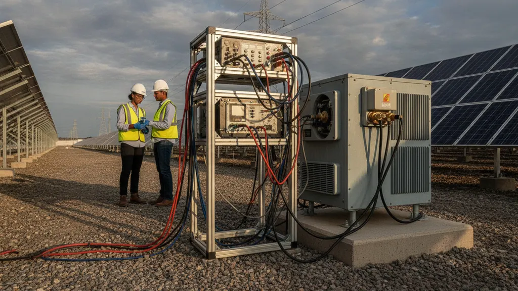
The final commissioning package includes the injection log, the calibrated PMU frequency trace, and the plant SCADA active power trace on the same time base. Any deviation greater than 10% between commanded and measured slope opens a punch list item. Utility-scale solar plants that fail the test cannot begin commercial dispatch and cannot draw payment from the LGIA counterparty until they retest.
Frequently asked questions
What is solar plant frequency response and why does it matter for utility-scale PV?
Solar plant frequency response is the coordinated adjustment of an inverter fleet active power output to arrest and correct grid frequency excursions. Inverter-based resources now supply enough of the US bulk power system that synchronous generators alone cannot maintain the 60 Hz interconnection standard during large-loss events. Under FERC Order 842, every new large solar generator above 20 MW must demonstrate this capability before commercial operation. The North American Electric Reliability Corporation tracks whether each balancing authority hits its annual response obligation under NERC BAL-003-2, feeding grid resilience metrics that ISOs and utility planners rely on. As inverter-based resources displace synchronous generation across the Eastern and Western Interconnections, this obligation grows more consequential each year because there is less physical inertia in the bulk power system to slow a frequency decline naturally.
How does FERC Order 842 apply to inverter-based resources?
FERC Order 842, issued in February 2018, closed the earlier carve-out that had exempted many inverter-based resources from primary frequency response duties. Any new large generator above 20 MW seeking bulk-system interconnection must now include a droop no wider than 5% and a dead-band no wider than 0.036 Hz in its Large Generator Interconnection Agreement, per the Federal Energy Regulatory Commission. The rule does not retroactively apply to existing plants, so retrofit projects usually take on frequency response after a repowering event or an owner-driven grid-service upgrade tied to a repowering interconnection amendment. Project developers planning a capacity repowering should confirm with their interconnection engineer whether the amendment triggers full Order 842 compliance, including new commissioning test documentation under the updated LGIA schedule.
What droop and dead-band settings does the power plant controller use?
The plant controller reads the substation frequency measurement, applies a dead-band of 0.036 Hz around the 60 Hz reference, and outside that band uses a droop curve at 5% or tighter to compute an active power correction. Most utility-scale operators run the settings at the FERC ceilings because they leave headroom for other grid services and simplify the interconnection study. The National Renewable Energy Laboratory publishes reference droop curves and solar plant frequency response tuning guidance in its inverter-based resource studies at NREL.gov, and interconnection engineers usually mirror those curves during the initial commissioning walkthrough. Sites in balancing authorities with tighter frequency performance records sometimes file for a narrower droop, such as 3%, to increase their headroom contribution and reduce the curtailment penalty on annual energy yield.
How is fast frequency response different from primary frequency response?
Primary frequency response is the slower, sustained active power adjustment inherited from synchronous governor action, delivered over roughly 10 to 30 seconds. Fast frequency response is a sub-second injection or absorption of active power delivered by inverter-based resources or a co-located BESS, per joint EPRI and NERC studies on inverter-based resource integration. FFR can arrive within 500 milliseconds of a disturbance, which is fast enough to arrest a frequency nadir before it triggers under-frequency load shedding. Both services coexist on the same solar plant: FFR handles the first swing and primary response takes over for the settlement window that BAL-003-2 measures. BESS-paired plants can stack both layers from the same asset by configuring the battery inverter for dP/dt inertia response under 200 ms and standard droop above 500 ms, producing a tiered profile that satisfies FFR program thresholds and the NERC BAL-003-2 measurement window in a single commissioning test package.
How does NERC BAL-003-2 calculate a balancing authority frequency response obligation?
NERC BAL-003-2 assigns each balancing authority a frequency response obligation (FRO) in megawatts per 0.1 Hz of frequency deviation, calculated annually from the prior year disturbance recordings under the frequency response sharing methodology. The FRO scales with the balancing authority share of interconnection demand and generation, plus the interconnection frequency bias setting. NERC publishes the current FRO values and the sharing group assignments in the BAL-003 attachments each year. Balancing authorities that miss the target for two consecutive years face compliance escalation with mitigation plans reviewed by the regional entity. Individual solar plants are rarely the balancing authority, but their commissioning records and ongoing SCADA data become evidence during a regional entity audit, which is why REIG engineers recommend retaining at least two years of 100 ms frequency and active power traces in the plant historian.
What tests validate solar plant frequency response during commissioning?
Commissioning testing runs a frequency injection at the plant controller frequency reference input, stepping the value from 60.000 Hz to 59.900 Hz and back to 60.036 Hz to walk through both dead-band edges and the droop slope. The witness engineer records active power at each step and compares the slope against the certified droop model. IEEE 1547-2018 defines the reference test sequence, and most interconnection agreements attach a modified version of that protocol. The final report becomes the primary evidence during ongoing NERC BAL-003-2 audits and any post-event review by the regional entity. Most interconnection owners also require the report to include a PMU calibration certificate dated within 12 months of the test and the PPC firmware version log, so the witness record is traceable to the exact software build that governed the plant during commissioning.