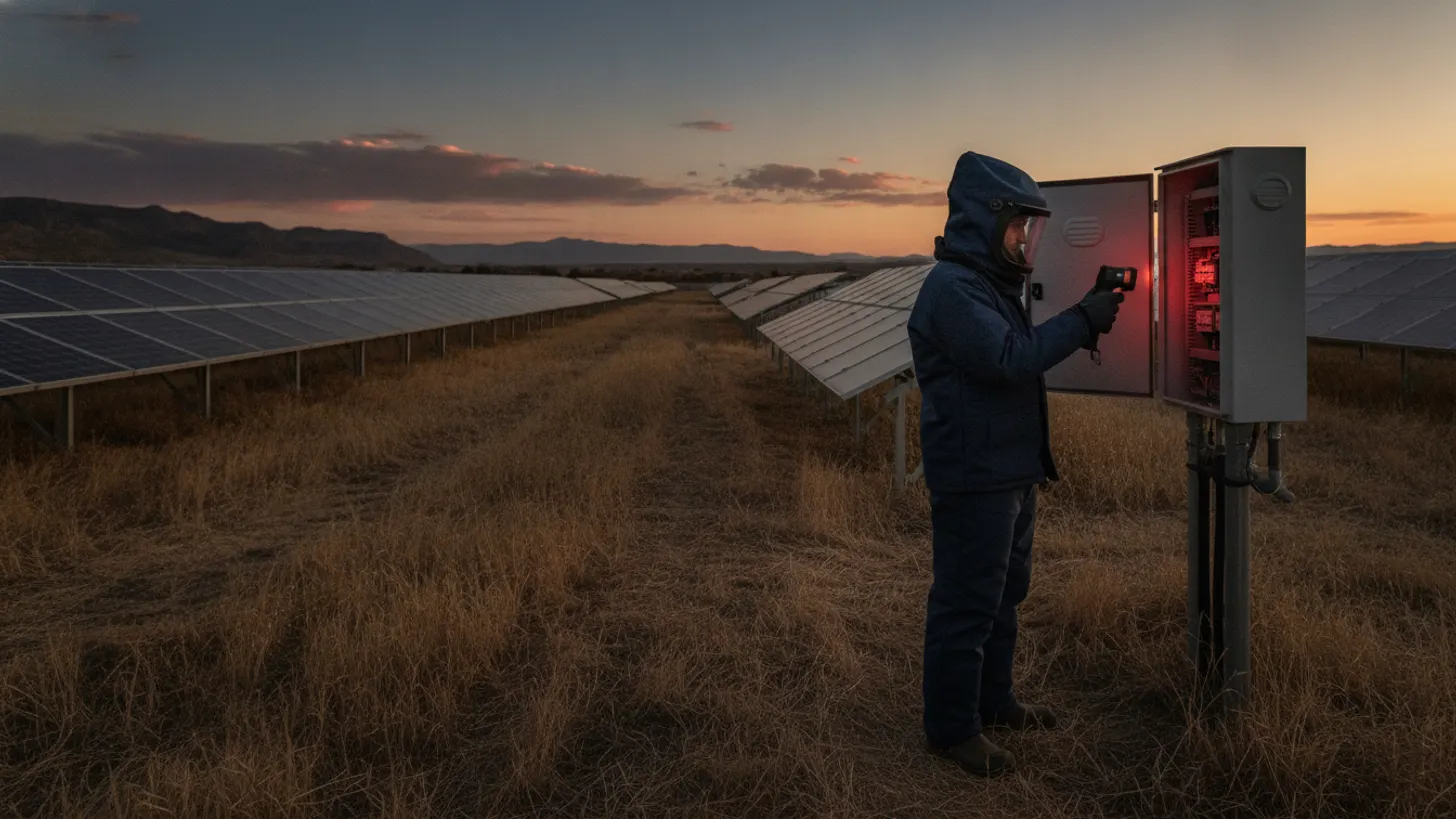
Solar farm arc flash analysis NFPA 70E: IEEE 1584 and PPE guide
A solar farm arc flash analysis NFPA 70E study is not an optional safety document at a utility-scale plant. IEEE 1584-2018 rewrote incident-energy math for three electrode configurations, NFPA 70E-2024 tightened PPE selection, and OSHA 29 CFR 1910.269 can pursue penalties up to $15,625 per citation for missing paperwork. This field guide walks EHS managers, EPCs, and O&M leads through what an accurate study requires.
Why solar farm arc flash analysis NFPA 70E differs from substation studies
A solar farm arc flash analysis NFPA 70E study covers hazard sources the substation short-circuit study never modeled: DC combiner boxes, string-level fuses, medium-voltage inverter output cabinets, and pad-mounted transformers scattered across the array field. Available fault currents behave differently on the DC side, and the substation model stops at the point of interconnection.
Utility-scale plants also introduce arc flash hazards inside the combiner-to-recombiner runs where NREL PV research has documented rising short-circuit contributions from higher-voltage strings. A separate PV-focused study captures those DC-specific hazards and produces incident energy numbers the EPC’s transmission report simply does not contain. Broader plant availability context lives in our solar SCADA downtime guide.
The scoping decision matters for compliance. If the O&M team relies on the interconnection study alone, PPE selection at the combiner will be under-rated, and the OSHA inspector will find no task-specific incident energy on file. A dedicated solar farm arc flash analysis NFPA 70E study, referenced against IEEE 1584-2018 for calculation methodology, closes both gaps in one document.
An O&M crew we supported at a 120 MW plant in South Carolina had used the interconnection study as the sole hazard reference for three years before an annual safety audit exposed the gap. When we ran a dedicated solar farm arc flash analysis NFPA 70E study on the DC side, several combiners calculated into Category 3; the crew had been working them in Category 1 gear. No incident had occurred, but corrective action required replacing all PPE kits site-wide and retraining every qualified worker before the plant could resume energized tasks.
For a closer look at this, see Solar Farm Revenue Metering: ANSI C12.20 Accuracy Field Guide.
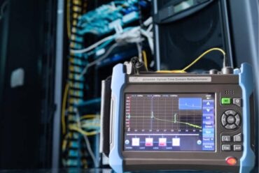
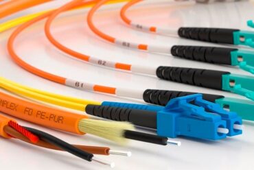
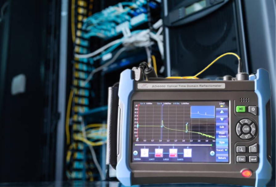
For a closer look at this, see Fiber optic installation solar farm: OTDR testing field guide.
There is a full breakdown of this topic in Solar farm lightning protection IEC 62305 and SPD field guide.
There is a full breakdown of this topic in Solar substation transformer differential protection: IEEE C37.91 guide.
We cover the details separately in Solar plant transformer DGA: dissolved gas analysis field guide.
IEEE 1584-2018 methodology inside solar farm arc flash analysis NFPA 70E
IEEE 1584-2018 discards the single empirical model of the 2002 revision and instead specifies three electrode configurations for calculating incident energy: vertical conductors in open air, vertical conductors terminated in a box, and horizontal conductors in a box. A solar farm arc flash analysis NFPA 70E study picks the configuration that matches each real cabinet on site.
The revised methodology produces materially different incident energy results for identical bolted fault currents compared with the 2002 method. The 2018 model was anchored by more than 1,800 arc flash test cases assembled through a joint research effort between EPRI and the IEEE P1584 working group; that test dataset is why the new standard specifies three electrode configurations rather than the single empirical curve of the prior edition. Studies published in IEEE standards materials show swings of 20 to 40% in calculated incident energy for identical bolted fault currents depending on electrode geometry, gap distance, and enclosure type. A cabinet that calculated at 8 cal/cm² under the 2002 method may recalculate at 11 cal/cm² or 5 cal/cm² under the 2018 box-electrode model, crossing a PPE category boundary in either direction. Every existing pre-2018 solar farm study should be re-run before the next NFPA 70E audit cycle.
On the DC side, the story is different again. Field studies indexed by the DOE Solar Energy Technologies Office show combiner-level arcing faults can sustain longer than AC arcs and behave in ways the classic AC 1584 model was never validated against. The industry has moved toward the DC arc energy method described in IEEE 1584.1 and referenced by IEC and IEEE working papers.
Bolted fault current inputs
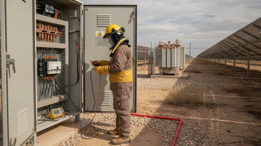
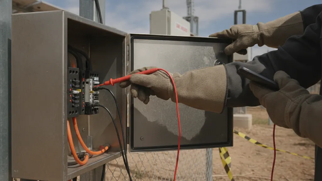
Accurate inputs come from the plant model, not the OEM datasheet alone. Combined inverter Isc contributions, string quantities, and cable impedances feed the fault model. A short-circuit study run against the exact single-line drives the incident energy math and gives each cabinet a defensible number.
For a closer look at this, see IEEE 1588 PTP Time Sync for Solar SCADA: GPS Clock Field Guide.
For a closer look at this, see IEEE 1547 solar interconnection: voltage ride-through guide.
For a closer look at this, see Solar plant AC grounding and ground grid design: IEEE 80 field guide.
NFPA 70E-2024 PPE categories inside solar farm arc flash analysis NFPA 70E
NFPA 70E-2024 Table 130.5(G) still assigns four PPE hazard categories running from 1.2 cal/cm² (Category 1) to 40 cal/cm² (Category 4). Where a solar farm arc flash analysis NFPA 70E study lands on the table depends on the DC voltage class, combiner string count, and available fault current at the terminal being worked.
Field experience across utility-scale plants shows DC-coupled combiner circuits with high string counts frequently calculate into Category 3 (25 cal/cm²) or Category 4 (40 cal/cm²). AC medium-voltage switchgear at 34.5 kV often falls into Category 2 or 3 depending on breaker interrupt speed. Low-voltage inverter LV terminals, if properly bonded, land at Category 1 or 2.
Two selection rules survive from earlier editions and are worth calling out for the O&M team: (1) if any part of a task pushes past 40 cal/cm², the task is not permitted with PPE alone and requires an energized work permit with additional controls per OSHA 29 CFR 1910.269; and (2) PPE is rated to arc thermal performance value (ATPV, the incident energy level at which a garment has a 50% probability of preventing second-degree burn injury under ASTM F1959 test protocols), and the site’s PPE program has to prove each garment’s rating traces back to that test documentation.
Category assignment example table
| Equipment class | Typical incident energy | PPE category |
|---|---|---|
| Inverter LV combiner terminal | 2 to 6 cal/cm² | Category 1 or 2 |
| DC combiner box, high string count | 10 to 28 cal/cm² | Category 3 |
| Recombiner enclosure | 12 to 30 cal/cm² | Category 3 or 4 |
| 34.5 kV MV switchgear | 8 to 18 cal/cm² | Category 2 or 3 |
| Pad-mounted transformer 34.5/0.6 kV | 14 to 22 cal/cm² | Category 3 |
Labels, re-issue, and change control after a solar farm arc flash analysis NFPA 70E study
Every cabinet within scope of a solar farm arc flash analysis NFPA 70E study receives a printed label per NFPA 70E Article 130.5(H). The label carries nominal voltage, arc flash boundary (the distance from an arcing source at which incident energy reaches 1.2 cal/cm², the onset threshold for second-degree burn), incident energy at the working distance, minimum PPE category, and the study date.
Labels are not one-and-done. Any modification that changes available fault current triggers a re-issue: new inverters, added string capacity, tap change on the interconnect transformer, or a substation upgrade at the point of interconnection. A five-year review cycle is standard practice and aligns with NFPA 70E Section 130.5 review requirements. Field labels also fade; UV-stable label stock is the minimum specification for outdoor DC combiners.
Document control matters as much as the label print. Our commissioning witness pack guide shows how to bundle the study calc report, single-line drawing revision that matches it, the PPE selection table, and the change log tying each label revision to a specific site modification. Auditors ask for that trail.
OSHA 1910.269 records that back your solar farm arc flash analysis NFPA 70E program
OSHA 29 CFR 1910.269(l)(8) is the federal enforcement side of a solar farm arc flash analysis NFPA 70E program. It requires the employer to assess arc flash hazard per task, provide PPE rated to the calculated incident energy, and retain hazard analysis records available on request.
Serious violations carry OSHA penalties up to $15,625 per citation as of 2024, and willful violations climb to $156,259. The OSHA penalties reference page tracks the current schedule; site EHS should review it annually. A missing hazard assessment counts as one citation; failure to provide correct-rated PPE counts as another; failure to train on the program is a third. OSHA electrical inspections at solar sites often run in parallel with contractor safety program audits, and citations issued to the host employer and the O&M contractor can accumulate independently. At a 200 MW plant with 20 qualified workers and incomplete hazard assessment records, per-instance citations under 29 CFR 1910.269(a)(2)(i) can push total penalties into six figures before willful-violation multipliers apply. Maintaining current records is not just a best-practice check but the primary defense if OSHA opens a targeted inspection after a reportable incident.
A complete solar farm arc flash analysis NFPA 70E program requires a living document package. Records to retain and update: the study calc report tied to a dated single-line, task-by-task hazard assessment, PPE issue log with ATPV traceability, refresher training records at three-year intervals, and site-specific work permits for any energized work above the arc flash boundary. Tie every entry to a personnel-identifiable ID; anonymous roll-ups do not satisfy the standard.

Integrating the program with SCADA and telemetry
Modern plants tie hazard status into SCADA alarm points so that a technician cannot dispatch to a cabinet with an unresolved incident energy exception. If your control platform already logs breaker positions and ground bank state, adding a hazard-status tag is a small change with a large safety upside. Our alarm-rule guidance covers the tag hygiene needed for that integration.
Frequently asked questions
How often does a solar farm need a new arc flash study?
NFPA 70E Section 130.5 sets a five-year review cycle, but any modification that changes available fault current triggers a re-study. That covers inverter swaps, added DC capacity, tap adjustments on the interconnect transformer, and utility-side changes at the point of interconnection. Sites should also re-run whenever OEM firmware updates change inverter Isc contributions or fault-clearing behavior. Practically, that means annual review of the change log, five-year full re-calculation, and interim re-runs on any modification tagged in the SCADA change-management workflow. The NFPA 70E standard remains the authoritative source. Assign a single responsible party, typically the plant EHS lead or the O&M engineering lead, to own the change-log review and flag the next re-study trigger before it surfaces during an OSHA audit or a NERC CIP documentation review cycle.
Do DC combiner boxes need their own arc flash calculation?
Yes. Combiner circuits behave differently from AC feeders because DC arcs can sustain longer and combiner-level string counts drive incident energy well above what the interconnection study models. IEEE 1584.1 offers a DC arc energy method the calculation engineer should apply for combiner and recombiner terminals. Field data indexed at the NREL research portal shows DC arc events tend to release more energy than an equivalent AC event before overcurrent clearing acts. Category 3 or Category 4 PPE is common for combiner tasks at high string counts; skipping the DC calc under-rates the PPE and violates 1910.269(l)(8). Request the calculation engineer’s scope letter before signing any O&M service agreement and verify the scope explicitly lists DC combiners and recombiners, not only the interconnection equipment covered by a transmission protection study.
Which PPE category do most solar site tasks fall into?
On a 100 to 300 MW plant, task mix generally lands with roughly 40% of tasks in Category 2, 32% in Category 3, 16% in Category 4, and the remainder in Category 1. Combiner work, MV switchgear operation, and pad-mounted transformer inspection push toward Category 3 and 4. Inverter LV work, when properly de-energized and grounded, drops to Category 1 or 2. The exact distribution depends on plant single-line, string counts, and interconnect impedance, so cross-check against the IEEE 1584 standards portal and the site’s own hazard assessment rather than assuming an industry average. Request the calc report task table from the study engineer and sort tasks by incident energy; any task above 12 cal/cm² should trigger a pre-task briefing and a signed work permit before the crew enters the arc flash boundary.
What documentation does OSHA expect at a plant audit?
The auditor typically asks for the study calc report, the single-line drawing that matches it, the task-by-task hazard assessment, the PPE issue log, training records for each qualified worker, and any energized work permits with signatures. Under OSHA electrical safety rules, each document must be current and traceable to a named worker. Missing any category invites a serious citation, and OSHA penalties reach $15,625 per citation as of 2024. Sites that align records with NERC CIP compliance practices and store records inside a controlled document system tied to the plant SCADA change log audit best. A practical document control step is to store all records in a controlled folder inside the plant SCADA document management system with revision numbers that match the single-line drawing, so any auditor can pull the current package without chasing individual engineers for file locations.
Can arc flash labels be printed in-house or must a third party issue them?
Either approach can be compliant. NFPA 70E Article 130.5(H) does not mandate an outside label vendor; it specifies label content and durability. Many plants print labels in-house from the calc report using UV-stable label stock. The requirement that matters most is that the label content matches the current study revision and that each label carries a study date. Third-party services can help sites with high volume or that lack an in-house engineering resource. If in-house, control the label print list inside your document management system so every re-issue triggers a paired removal of the outdated label, per IEC labeling guidance. Assign a label sequence number that matches the panel ID in your SCADA asset database so a work order system can flag stale labels automatically when a study revision posts, removing the manual label-hunting step that delays maintenance crews.
How does the DC arc flash risk differ from the AC side?
DC arcs do not have a natural current zero crossing, so an initiated DC arc can sustain until overcurrent protection clears or the arc migrates out of the fault volume. The classic AC-only IEEE 1584-2002 model was never validated against that behavior. IEEE 1584.1 and referenced IEC papers on DC arc flash use different equations and different clearing-time assumptions. A plant with high DC string voltage above 1500 V compounds the risk. Practically, DC combiner tasks often require Category 3 or 4 PPE and a lockout procedure that verifies zero energy at both DC input and combiner output before touching terminals. The DOE clean energy resources host related field research. Confirm that the calculation engineer’s scope statement references IEEE 1584.1 or an equivalent DC arc energy method and that the protective relay coordination study for the DC side has been handed to the incident energy calculation team before they finalize clearing times.