

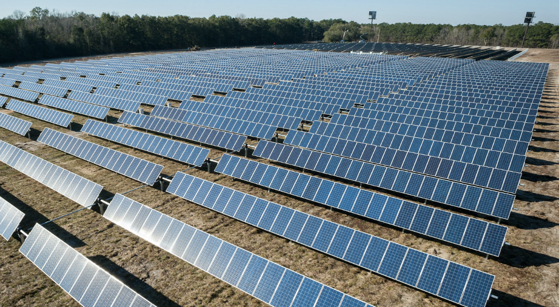
IEEE 1547 solar interconnection: voltage ride-through guide
The IEEE 1547-2018 standard rewrote the rules for IEEE 1547 solar interconnection by replacing a single low-voltage trip with three ride-through categories, requiring Category III inverters to stay online at 0 per-unit voltage for up to one full second. For utility-scale plant owners and EPCs, that change shifted the burden from passive disconnection to active grid support, with reactive power, frequency response, and SCADA setpoints all part of the witness testing scope.
What changed in IEEE 1547 solar interconnection from 2003 to 2018
The original IEEE 1547-2003 directed distributed energy resources to disconnect on any abnormal voltage or frequency. IEEE 1547-2018 reverses that posture: utility-scale solar plants must now actively support the grid through voltage ride-through, frequency ride-through, autonomous reactive power, and ramp-rate control, with disconnection reserved for actual fault conditions.
The driver was scale. As US solar penetration climbed past 100 GW per the DOE Solar Futures Study, the 2003 trip-on-disturbance model became a liability for any modern IEEE 1547 solar interconnection: a single fault could disconnect hundreds of megawatts of generation in milliseconds, propagating instability rather than containing it. The August 2016 Blue Cut Fire transmission disturbance in the CAISO footprint disconnected approximately 1,200 MW of utility-scale solar within seconds because inverters were programmed to trip on voltage sag under the 2003 standard. The NERC inverter-based resource performance guideline documented that event and several others as the operational case for rewriting DER interconnection requirements.
IEEE 1547-2018 published in April 2018 and was approved by FERC for use in interconnection studies. State adoption is staged: California, Hawaii, and New York moved first, while several southeastern utilities, including Duke Energy Progress in the Carolinas, began enforcing the standard for new IEEE 1547 solar interconnection applications between 2021 and 2023. EPC project managers should confirm which version their utility currently enforces before locking inverter selection.
| Requirement | IEEE 1547-2003 | IEEE 1547-2018 |
|---|---|---|
| Low-voltage response | Trip immediately on any abnormal voltage | Ride through by category; Category III holds at 0 p.u. for 1.0 s |
| Ride-through categories | None (single trip threshold) | Three categories (I, II, III) by DER system impact level |
| Reactive power at POI | Not required | 0.95 lag to 0.95 lead, dynamic (FERC Order 827) |
| Autonomous reactive injection | Not required | Required under Section 7.4 without utility dispatch signal |
| Ramp-rate control | Not required | Required; configurable by host utility |
Voltage ride-through categories under IEEE 1547 solar interconnection
IEEE 1547-2018 defines three voltage ride-through categories. Category I is the minimum required capability, Category II is intermediate, and Category III is the most demanding, designed for DERs whose disconnection would affect bulk system stability. Utility-scale solar plants almost always fall under Category III.
Category III inverters must remain connected at 0 per-unit voltage for up to 1.0 second, ride through deeper sags than Category I or II, and resume normal output afterward without manual reset. Category II covers a moderate ride-through envelope and is common in commercial-scale aggregation. Category I, the legacy-equivalent profile, applies to small DER on weak feeders where ride-through is less material to the bulk system.
| Feature | Category I | Category II | Category III |
|---|---|---|---|
| Typical application | Small DER on weak distribution feeders | Aggregated or commercial-scale DER | Utility-scale solar with bulk-system impact |
| Must-ride-through at 0 p.u. | 0.16 s | 0.32 s | 1.0 s |
| Reactive power modes (Section 7) | All four modes applicable | All four modes applicable | All four modes applicable; FERC Order 827 range required at POI |
| Who assigns the category | Host utility interconnection study | Host utility interconnection study | Host utility interconnection study; virtually universal for utility-scale solar |
Selecting a Category III inverter is not optional once a utility flags the plant as bulk-system relevant. Owners who specify Category II inverters for a Category III interconnection face either re-purchase or refused energization, and witness testing under IEEE 1547.1-2020 will catch the mismatch. Confirm category selection during the IEEE 1547 solar interconnection feasibility study, not after equipment is on site.
Reactive power and power factor mandates at the point of interconnection
FERC Order 827, issued in 2016, requires new large generators to provide dynamic reactive power capability across a power factor range of 0.95 lagging to 0.95 leading at the point of interconnection per FERC Order 827. IEEE 1547-2018 implements this obligation at the DER level through four autonomous reactive control modes defined in Section 7: Volt-VAR, constant power factor, watt-VAR, and constant reactive power.
The distinction between inverter-terminal capability and POI capability matters. An inverter rated at unity power factor at its AC terminals cannot deliver 0.95 leading at the POI once collection-system losses and step-up transformer reactive consumption are netted. Plant designers must size inverter MVA, capacitor banks, and STATCOM compensation to land within the FERC envelope after losses. See our explainer on utility-scale monitoring versus SCADA roles for the measurement chain that feeds POI calculations.
Section 7.4 of the 2018 standard requires DER systems to inject reactive power autonomously during voltage disturbances, without waiting on a utility dispatch signal. That requirement removes the round-trip latency between the utility EMS and the plant DCS, which under the 2003 standard could exceed several seconds. The inverter and PPC must respond on the local voltage measurement alone, within the response time required by the configured mode (typically a 1 to 10 second open-loop response per EPRI guidance on smart inverter functions). That autonomy is the defining architectural shift in IEEE 1547 solar interconnection design.
How SCADA enforces IEEE 1547 solar interconnection setpoints in real time
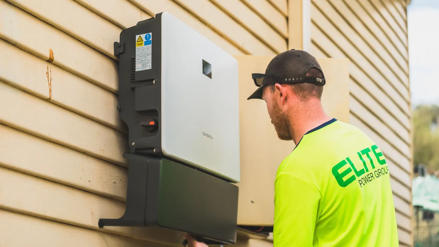
Enforcing IEEE 1547 solar interconnection setpoints requires the SCADA system and plant controller to write reactive power, voltage, and ramp-rate targets to every inverter at sub-second cadence. The PPC polls inverters using SunSpec Modbus or DNP3, holds limits during disturbances, and logs every set-point change for compliance audits.
A typical architecture splits responsibility cleanly. The PPC owns the closed loop on POI voltage and reactive power, computing inverter-level setpoints from a real-time POI measurement. SCADA owns visualization, alarming, historization, and the operator HMI. Both feed a long-term historian that the utility can request during an investigation. Brian Otto and REIG’s commissioning teams have validated this architecture across Category III sites in the Carolinas and Georgia, working with Sungrow and SMA inverter platforms where SunSpec Modbus register selection for Volt-VAR mode required pre-witness coordination with OEM application engineering teams to confirm firmware support. See our breakdown of plant controller setpoints and limits for the wiring details.
Protocol choice carries compliance weight. SunSpec Modbus has standardized register maps for the IEEE 1547-2018 smart inverter functions, which simplifies acceptance testing. DNP3 with secure authentication is preferred where the plant falls in scope for NERC CIP because set-point writes are recorded with cryptographic integrity. Our SunSpec register map guide covers both stacks for utility-scale IEEE 1547 solar interconnection projects, and the IEC 61850 substation guide describes how the same setpoints propagate to the HV bay controllers.
Historian configuration is where most plants slip. IEEE 1547.1-2020 testing expects time-aligned, sub-second logs of inverter mode, set-point, measured voltage, and reactive power output across the disturbance window. A historian sampling at 5-second cadence cannot reconstruct the ride-through behavior. Configure the historian or a separate PMU stream at 30 to 60 samples per second on the disturbance points before commissioning.
We cover the details separately in IEEE 1588 PTP Time Sync for Solar SCADA: GPS Clock Field Guide.
For a closer look at this, see IEEE 1588 PTP Time Sync for Solar SCADA: GPS Clock Field Guide.
Utility witness testing and documentation for IEEE 1547 solar interconnection approval
Utility witness for IEEE 1547 solar interconnection covers commissioning tests against IEEE 1547.1-2020, the companion conformance testing standard. For a Category III plant, the on-site sequence typically spans two to three days, covering ride-through at multiple voltage levels, reactive power capability across the full 0.95 lag to 0.95 lead range, and verification of all four IEEE 1547-2018 reactive control modes.
Two failure modes are common. First, inverter type-test certificates from the manufacturer are mistaken for plant-level commissioning evidence. The utility wants both: the type test plus an as-built site-specific demonstration. Second, the Volt-VAR curve loaded into the inverter does not match the curve filed in the interconnection agreement. In our pre-witness walk at a 2023 North Carolina Category III site, three of six inverters carried Volt-VAR curve parameters that did not match the filed interconnection agreement, a discrepancy that would have stopped the witness test and pushed energization out by several weeks. Reconcile every parameter the day before the witness with a screenshot per inverter, signed by the commissioning engineer. Our witness pack guide walks through the artifacts a transmission operator typically expects.

Documentation that survives audit also covers cybersecurity for the IEEE 1547 set-point writes. NERC CIP-005 and CIP-007 expectations apply when the inverter set-point path crosses an Electronic Security Perimeter, and the witness team will sample evidence of patch management, account controls, and logging on the PPC and SCADA hosts.
Frequently asked questions
What is IEEE 1547-2018 and how does it differ from IEEE 1547-2003?
IEEE 1547-2018 is the current US standard for interconnecting distributed energy resources, including utility-scale solar, with the bulk electric system. It replaces IEEE 1547-2003, which directed inverters to disconnect on any abnormal grid condition. The 2018 revision instead requires inverters to ride through disturbances and actively support the grid with reactive power, voltage regulation, and frequency response. According to the IEEE 1547-2018 standard page, the rewrite was driven by rising DER penetration that made trip-on-disturbance behavior a reliability risk rather than a safety feature for the modern grid.
Which voltage ride-through category applies to a 100 MW solar plant?
A 100 MW utility-scale solar plant almost always falls under Category III of IEEE 1547-2018 because its disconnection would affect bulk system stability. Category I is reserved for smaller DERs on weak feeders, and Category II covers moderate aggregation. The interconnection study performed by the host utility or independent system operator determines the formal category assignment based on the plant’s electrical influence and the local grid topology. The NERC inverter-based resource performance guideline explains how operators classify plants and why Category III prevails for utility-scale solar.
How long must a Category III inverter ride through a voltage sag to zero?
IEEE 1547-2018 requires a Category III inverter to remain connected at 0 per-unit voltage for up to 1.0 second before any permitted trip. The inverter must resume normal output once voltage recovers, without manual operator intervention. This is a sharp departure from IEEE 1547-2003, which directed the inverter to trip almost immediately on low voltage. The 1.0 second hold lets transmission operators clear faults using normal protection coordination without losing distributed generation in the process, which is the central premise of the rewritten standard documented by the IEEE 1547-2018 working group.
What reactive power range does FERC Order 827 require?
FERC Order 827, issued in June 2016, requires new large generators including utility-scale solar plants to provide dynamic reactive power capability across a power factor range of 0.95 lagging to 0.95 leading, measured at the point of interconnection. The requirement is dynamic, not static, so capacitor banks alone do not satisfy it; the plant must vary reactive output continuously in response to grid conditions. FERC Order 827 is the controlling document, and the obligation is recorded in the Large Generator Interconnection Agreement that every new utility-scale plant signs with the host transmission operator.
When must a legacy plant retrofit to meet IEEE 1547 solar interconnection 2018 rules?
Existing plants are generally grandfathered under the IEEE 1547 version active at the time of their interconnection agreement, but several states and operators are now requiring retrofits for material modifications, capacity increases, or repowers. A few transmission operators have asked legacy plants to update their voltage and frequency trip settings to match the wider IEEE 1547-2018 ride-through envelope, especially in regions with high inverter-based generation density. The DOE Solar Futures Study covers the policy direction. Confirm retrofit obligations with your host utility before any plant modification.
Who certifies IEEE 1547 solar interconnection compliance for a new plant?
Inverter conformance to IEEE 1547-2018 is verified through type testing per IEEE 1547.1-2020, the companion conformance testing standard. Nationally recognized testing laboratories such as Intertek, UL, and CSA perform the type tests and issue certificates that the manufacturer ships with the inverter. The utility then witnesses a site-specific commissioning test using IEEE 1547.1-2020 procedures to verify the as-built plant matches the certified equipment and the interconnection agreement parameters. IEEE 1547.1-2020 defines the procedures the witness team follows on site.


