
DC Ground Fault Detection in Utility-Scale Solar: NEC 690.5 Field Guide
NREL’s 2012 PV fire incident analysis traced a material share of array fires to ground faults combined with weak protection coordination in early transformer-less inverter designs. Solar DC ground fault detection under NEC 690.5 exists to interrupt those events before the DC bus can sustain destructive current. This field guide walks utility-scale commissioning engineers through the code requirements, isolation monitoring behavior, arc fault interrupter coordination, and pre-energization tests that keep multi-megawatt collection systems from becoming ignition sources.
What NEC 690.5 requires for solar DC ground fault detection
Solar DC ground fault detection under NEC 690.5 obliges the designer to install a device that detects fault current between an energized DC conductor and ground, interrupts the faulted circuit automatically, and provides an indication that a fault has occurred. The 2023 edition tightened language around forced disconnection of the affected string.
The 2020 and 2023 code cycles closed a gap that older 690.5 language left open. Earlier revisions permitted the protection device to disconnect only the ground bond rather than the faulted circuit itself, which let leakage keep flowing. Guidance from the DOE Solar Energy Technologies Office and the NREL 2012 PV fire incident analysis pushed subsequent revisions to force disconnection of the faulted circuit, not just annunciation.
On a 20 MW utility-scale block with 40 combiner boxes and 800 strings, a single unresolved ground fault can drive circulating DC current that damages inverter isolation transformers within hours. That failure mode is documented in EIA capacity reports on premature inverter replacement rates at plants over 10 years old. Ground fault protection that fails to disconnect the faulted circuit lets thermal damage compound.
Grounded vs ungrounded utility-scale array behavior
Grounded arrays typically bond the negative DC rail through a ground fault protection assembly. When leakage exceeds the assembly’s trip threshold (commonly 1 A for combiner-level protection on multi-megawatt strings), the assembly opens and blocks the fault path. Ungrounded arrays use an isolation monitoring device that continuously measures resistance between each pole and earth. The device triggers an alarm and fault contact well before insulation degradation reaches short-circuit levels. Both topologies must still meet the IEC 62548:2016 boundary: trip thresholds must not exceed 30 mA where human contact with live conductors is reasonably foreseeable during operation or maintenance.
The distinction matters when specifying equipment. Utility-scale string inverters with transformer-less topologies, such as the Fronius Tauro or the SMA Core1, present floating DC buses that require an isolation monitoring device as the primary ground fault sensor. Central inverters with internal line-frequency isolation transformers, such as the SMA Sunny Central series, support a grounded DC architecture where a conventional GFDI relay on the negative bus is the primary protection device. Choosing the wrong solar DC ground fault detection topology for the inverter architecture is a wiring error that commissioning testing will catch, but that redesign and re-termination work are required to correct.
How isolation monitoring devices power solar DC ground fault detection at utility-scale
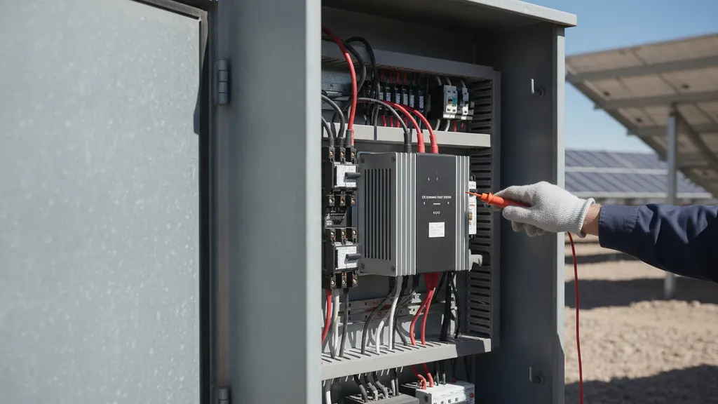
Isolation monitoring devices drive solar DC ground fault detection on ungrounded and transformer-less inverter topologies by injecting a low-frequency probe signal between the DC bus and ground, then measuring how much of it returns. A drop in isolation resistance below the configured threshold indicates leakage. On multi-megawatt DC collection systems, IMDs behave differently than they do on residential strings.
On a 5 MW block, the effective capacitance between the DC conductors and ground can reach several microfarads. That capacitance stretches the probe cycle time and can mask small leakage events if the IMD threshold is set too tight. IEC 62109 recommends tuning the trip threshold to plant capacitance rather than accepting the manufacturer default. IEEE PES working group publications on PV plant safety reinforce this guidance with utility-scale field data.
The IMD injection frequency also matters. A 2.5 Hz probe signal that works well on a 100 kW string can be blind to certain resistive faults on a 5 MW block because the DC bus impedance changes shape. Plant designers should require the IMD spec to name the injection frequency and its capacitance tolerance, then verify against the actual as-built collection system capacitance during commissioning.
For a closer look at this, see SunSpec Modbus inverter: register maps for utility-scale solar plants.
For a closer look at this, see BESS SCADA Integration for Utility-Scale Solar Plants: A Field Guide.
For a closer look at this, see Utility Scale Solar Monitoring vs SCADA: Roles and Layers Defined.
For a closer look at this, see Solar SCADA cybersecurity NERC CIP: utility-scale compliance guide.
For a closer look at this, see Solar SCADA Alarm Rules: Cut Nuisance Noise on Utility-Scale Plants.
For a closer look at this, see Modbus TCP vs DNP3: solar SCADA protocol guide for utility plants.
For a closer look at this, see How solar SCADA reduces unplanned downtime at utility-scale plants.
For a closer look at this, see Solar drone thermal inspection: utility-scale hotspot field guide.
For a closer look at this, see Solar Curtailment and AGC in Utility-Scale Solar Plant Operations.
For a closer look at this, see Solar SCADA commissioning: building the utility witness pack.
For a closer look at this, see Solar plant SCADA system modernization: a utility upgrade roadmap.
AFCI coordination differs from solar DC ground fault detection under NEC 690.11
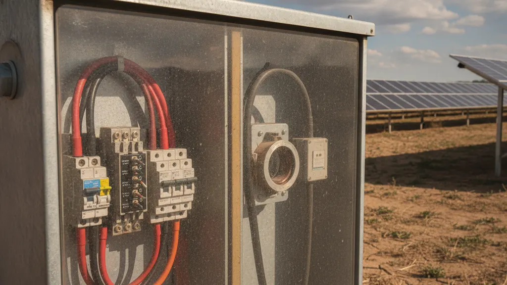
AFCI coordination and ground fault protection address distinct failure modes at utility-scale plants. NEC 690.5 catches parallel current between an energized conductor and ground. NEC 690.11 catches series arc signatures within a conductor path, most commonly at loose combiner box terminations or degraded MC4 connectors. The two systems must both function, and their alarms must appear as separate points in SCADA.
Series arcs on a 1500 V DC string generate broadband RF and specific current signal envelopes that AFCI logic recognizes. A ground fault, in contrast, is a low-frequency leakage event. If a plant’s SCADA merges the two alarm classes into one summary point, the operator loses the ability to diagnose whether the trip was caused by an insulation failure or a connector fault. Both root causes need different remediation crews, so alarm architecture matters.
OSHA guidance on DC electrical hazards reinforces this separation for utility-scale plant operators, and our solar farm arc flash analysis field guide covers the personnel protection side of energizing a DC bus.
Coordinating protection thresholds across string, combiner, and inverter levels
Coordinated protection uses different trip thresholds and delays at each level so only the closest device opens for a given fault. A poorly coordinated plant trips the entire inverter block for a single string fault, masking fault location and burning revenue. Solar DC ground fault detection coordination is a table with four columns: level, threshold, delay, and disconnection scope.
| Protection level | Typical trip threshold | Delay | Disconnection scope |
|---|---|---|---|
| String fuse or midcombiner | 1.25x Isc | Fast (I2t) | Single string |
| Combiner-level GFDI | 1 A leakage | 50 to 100 ms | Combiner and downstream strings |
| Inverter internal GFDI | 300 mA to 5 A | 100 to 500 ms | Inverter DC input |
| Isolation monitor (ungrounded) | R below 1 kohm per V | Continuous trend plus alarm | Alarm only, no auto-disconnect |
Time coordination matters as much as current coordination. If the inverter GFDI clears in 100 ms and the upstream combiner GFDI clears in 200 ms, then a string-level fault will always be cleared by the combiner. That is the goal. Reverse the delays and every string fault will drop the inverter. Consult protection selectivity literature from a licensed protection engineer if you need a formal coordination study workflow. Our SCADA alarm rules guide covers the annunciation side of the same tradeoff.
In 2021, on a 50 MW project in central North Carolina, our commissioning team discovered that the inverter GFDI clearing time had been shipped from the factory at 100 ms while the upstream combiner GFDI was set to 200 ms. That reversal undermined solar DC ground fault detection selectivity for the entire site: every string-level fault during the first three weeks of generation dropped the inverter block. It took two rounds of protection coordination study revisions to correct. REIG now requires a signed protection coordination table from the equipment vendor before any DC energization permit is issued.
Field tests that verify solar DC ground fault detection before energization
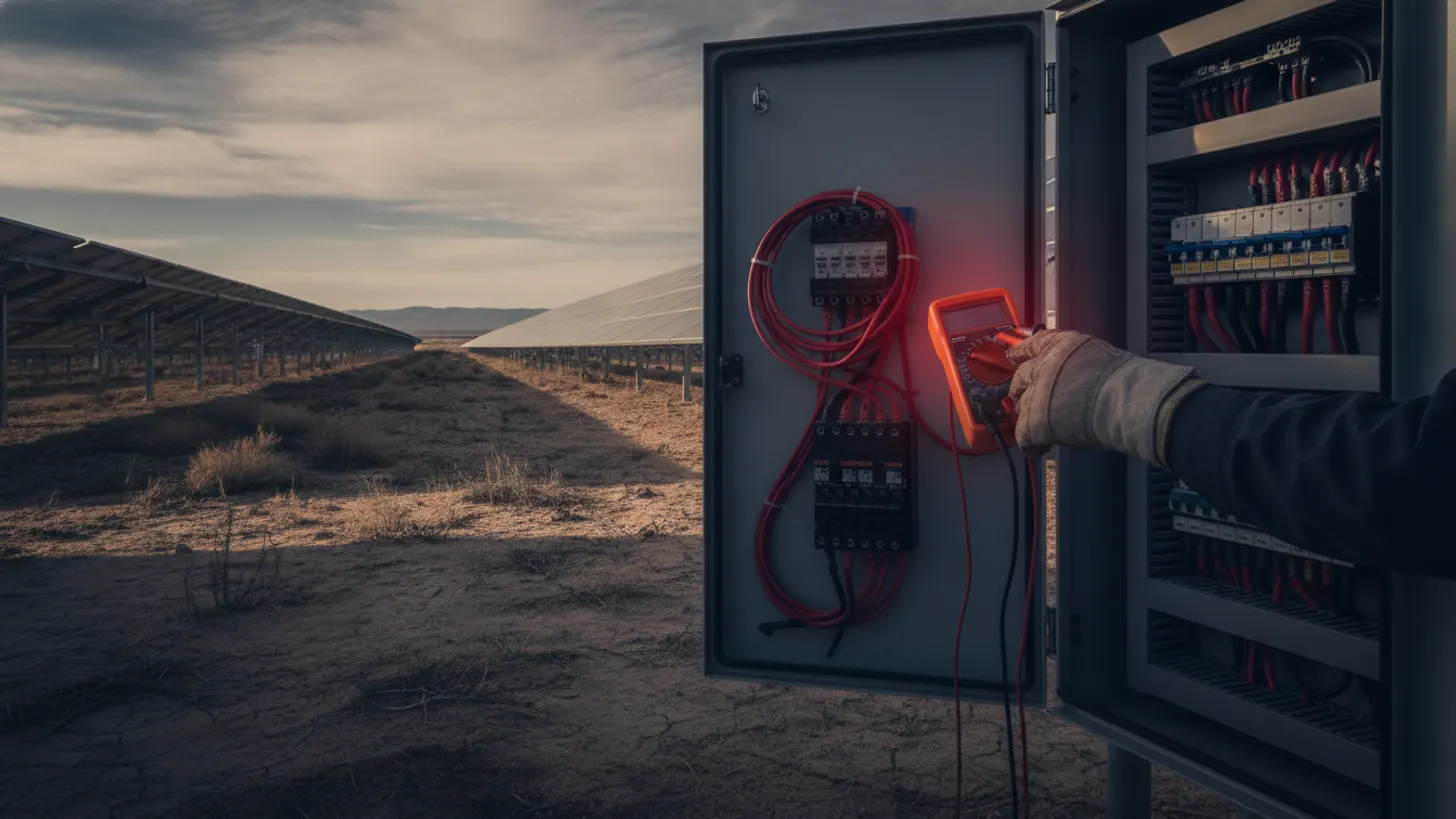
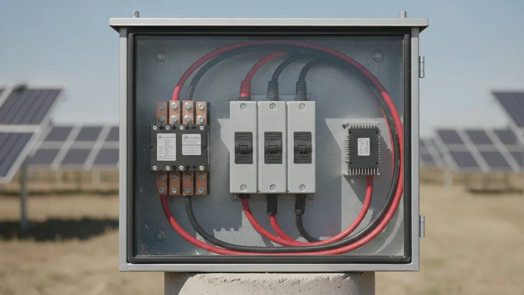
Field verification of solar DC ground fault detection combines insulation resistance measurement, simulated fault injection, and a documented functional trip test at each level of coordination. These tests are ideally witnessed by the interconnection utility and captured in the commissioning packet before the DC bus is energized to grid voltage. Skipping any one of the three creates a hidden failure mode.
Insulation resistance testing (megger test) applies 500 V or 1000 V DC between conductors and ground and reads the resistance in megohms. IEC 62446-1 specifies pass thresholds by string voltage. Simulated fault injection uses a controlled resistance box between the DC conductor and ground bus to confirm the GFDI trips at the expected leakage level. The functional test verifies that the disconnect actuates and that the SCADA alarm reaches the operator interface.
The EPRI test protocol documents the acceptance sequence in detail, and the DOE SETO program funds test standardization for utility-scale plants. Our solar SCADA commissioning witness pack and DAS commissioning field guide cover the paperwork side.
For a closer look at this, see IEEE 1588 PTP Time Sync for Solar SCADA: GPS Clock Field Guide.
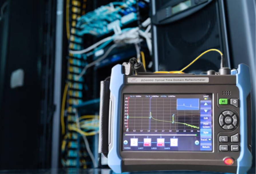
For a closer look at this, see Fiber optic installation solar farm: OTDR testing field guide.
For a closer look at this, see Solar Farm Revenue Metering: ANSI C12.20 Accuracy Field Guide.
We cover the details separately in Solar plant AC grounding and ground grid design: IEEE 80 field guide.
For a closer look at this, see Solar string IV curve tracing: field methods for degradation detection.
There is a full breakdown of this topic in Solar farm lightning protection IEC 62305 and SPD field guide.
There is a full breakdown of this topic in Solar plant transformer DGA: dissolved gas analysis field guide.
Frequently asked questions
What NEC 690.5 trip threshold is standard for utility-scale combiner-level solar DC ground fault detection?
Combiner-level GFDI on 1500 V utility-scale DC blocks is typically set at 1 A leakage with a 50 to 100 ms clearing time. This value is not codified in NEC 690.5 itself; the code requires disconnection of the faulted circuit but leaves the threshold to the equipment manufacturer and the coordination study. NEC 690.5(B) specifies that the GFDI must automatically disconnect the faulted circuit and provide indication that a fault has occurred. Values in the field cluster around 1 A because that level trips reliably on real ground faults without nuisance-tripping on capacitive charging currents from the array, which is the primary calibration challenge in solar DC ground fault detection on large-capacitance DC bus systems. Reference the IEC 62109-2 guidance on inverter fault detection for the underlying methodology used across most utility-scale designs.
How does an isolation monitoring device differ from a ground fault detector on a utility-scale array?
A ground fault detector reacts to a fault after leakage current has already begun flowing. An isolation monitoring device measures DC bus insulation resistance continuously and issues an alarm when insulation degrades, well before a fault current exists. IEC 62109-2 requires transformer-less inverters to include an isolation monitoring function capable of detecting insulation resistance drops below 1 kohm per volt of system voltage, which on a 1500 V DC bus means an alarm threshold at or above 1.5 megohms. On ungrounded and transformer-less inverter topologies, IMDs are the primary safety layer because there is no bonded return path for a classic GFDI to sense. The NREL PV reliability program documents both approaches as complementary rather than substitutes on multi-megawatt systems.
How does AFCI arc fault protection under NEC 690.11 differ from NEC 690.5 ground fault detection?
NEC 690.11 targets series arcs, which are broadband RF and current-envelope signatures inside a conductor path (usually at a degraded connection point or a loose MC4 connector under load). NEC 690.5 targets parallel leakage current between a live conductor and ground. The two are physically different fault modes, so AFCI uses signal processing on RF spectrum and current derivatives, while GFDI uses simple leakage current measurement. Both must operate and both must be independently annunciated to the plant SCADA, so operators can dispatch the correct remediation crew for each fault type.
What insulation resistance value passes a pre-energization test on a 1500 V DC string?
IEC 62446-1 specifies a minimum insulation resistance of 1 megohm for systems above 1000 V DC when the test voltage is at least the system voltage. In practice, commissioning engineers reject anything under 5 megohms at 1000 V test voltage, because values in that range typically indicate degrading jacket insulation that will trip GFDI within months of energization. The EPRI field test protocols for utility-scale PV recommend the tighter threshold as a leading indicator of long-term reliability, and IEC 62446-1 requires the megohmmeter reading to stabilize for 60 seconds before the value is recorded as the pass or fail result.
Can a plant SCADA system reset a GFDI trip remotely without a technician visit?
No. NEC and OSHA guidance both require that a ground fault clearing device only be reset after the fault has been located and cleared. Remote reset without physical inspection risks re-energizing a still-faulted conductor, which is precisely what the disconnection requirement is written to prevent. The OSHA electrical safety program treats a live conductor with unresolved leakage as a hazard requiring lockout tagout before any reset attempt. Plant SCADA should annunciate the trip but block automatic reset paths at the operator workstation.
How often should isolation monitoring devices be re-verified after commissioning?
Annual verification is the field consensus. IMD calibration drifts slowly with electrolytic component aging in the injection circuit, and a device that reads healthy in year one can under-report leakage by year five. Compare the IMD reading against a portable megohmmeter measurement on a de-energized string, ideally during the same annual maintenance window as the drone thermal inspection. An IMD that has drifted more than 20 percent from its factory calibration can produce false-healthy readings on strings already showing early jacket degradation, which delays fault detection by months. DOE SETO reliability program data supports the annual verification cadence for utility-scale plants.