Protection relay testing solar substation secondary injection guide
Utility protection reviewers reject roughly one in three interconnection witness submissions on first pass, most often for gaps in protection relay testing solar substation records. Every rejection can slip a project’s commercial operation date by weeks. REIG crews have prepared more than 60 secondary injection witness packages across 14 states, and the same documentation gaps surface each time. Secondary injection, when scoped against IEEE C37.233 and NERC PRC-005-6, forecloses that risk by proving each relay element under calibrated stimulus before energization. This field guide walks through the workflow, the acceptance thresholds, and the report layout utility engineers expect from a solar substation commissioning package.
What secondary injection means for protection relay testing solar substation crews
Secondary injection disconnects a relay from its instrument-transformer secondary wiring and drives each of its 8 to 15 enabled elements through a calibrated current and voltage source. For protection relay testing solar substation teams, that isolation proves every function without energizing the collector bus, GSU, or high-side breaker, per IEEE C37.233-2009.
Primary injection remains useful for validating the entire loop from current transformer through relay to trip coil, but it is slow, requires high-current sources, and is rarely practical for a whole substation’s relay complement. Secondary injection sidesteps those constraints. A modern amplified test set can source hundreds of amps at instrument-transformer secondary levels while measuring millisecond trip-contact closures, giving crews the throughput to test 20 or more relays in a shift.
The technique is codified in the IEEE C37.233 Guide for Power System Protection Testing, which spells out setup, pickup verification, trip-time measurement, and reset behavior for each protection element class. Following the guide keeps your data comparable across projects and, more importantly, matches the acceptance rubric utility reviewers apply when they scrutinize your witness package.
For utility-scale plants, SCADA integration adds a second reason to test carefully. Every trip and lockout signal in your relay logic maps to a DNP3 or IEC 61850 tag that drives HMI alarms, event logs, and remedial action schemes. If secondary injection reveals a mis-mapped bit, you find it before energization instead of during a phase-A fault at 2 a.m.
We cover the details separately in Solar substation transformer differential protection: IEEE C37.91 guide.
For a closer look at this, see Solar DC cable insulation testing: HIPOT and megger commissioning guide.
For a closer look at this, see Solar substation IEC 61850 GOOSE messaging: relay protection guide.
We cover the details separately in Solar farm lightning protection IEC 62305 and SPD field guide.
For a closer look at this, see IEC 61850 Solar Substation: GOOSE, MMS, and Sampled Values Guide.
Which functions must be covered in protection relay testing solar substation packages
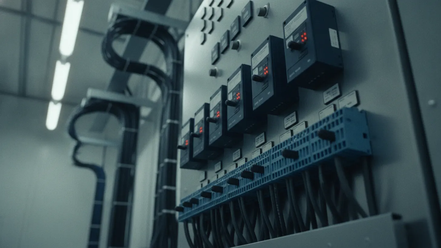
A complete protection relay testing solar substation scope covers every ANSI device function in the settings file. A typical GSU relay runs 6 to 8 primary protection elements: 87T transformer differential, 50/51 phase and ground overcurrent, 27/59 under and overvoltage, 81 under and overfrequency, and 50BF breaker failure. Collector feeder relays add sensitive earth fault and directional overcurrent.
The interconnection breaker relay is normally the most function-heavy device in the substation, coordinating with the utility’s transmission protection. Distance elements, out-of-step blocking, synchro-check, and dead-line dead-bus reclose logic all appear here, and each must be verified under stimulus that matches the utility’s approved settings sheet.
Auxiliary logic deserves the same rigor as protection elements. Trip-and-lockout paths through 86 lockout relays, breaker-status supervision, and 25 synchro-check permissives are common witness-package failure points because commissioning teams treat them as afterthoughts. Inject a test signal, watch the target lamp, confirm the SCADA event log annotates the trip, then repeat for every credible input combination.
Battery-backed DC control circuit integrity belongs in the plan as well. NERC PRC-005-6 explicitly names DC supply and control circuitry as part of the protection system subject to periodic verification. A relay that passes secondary injection but sits behind a marginal DC bus will still fail at operational moment. Reference the NERC PRC-005-6 standard text for the full component list.
| ANSI device | Function | Typical acceptance |
|---|---|---|
| 50/51 | Phase overcurrent (instantaneous/time) | Pickup ±3 to 5%, curve time ±5% |
| 87T | Transformer differential | Slope pickup ±5%, harmonic restraint verified |
| 27/59 | Under/overvoltage | Pickup ±3%, timing ±1 cycle |
| 81 U/O | Under/overfrequency | Pickup ±0.02 Hz, timing ±3 cycles |
| 21 | Distance | Reach ±5%, zone timing ±1 cycle |
| 50BF | Breaker failure | Timer accuracy ±1 cycle |
Configuring your test set for protection relay testing solar substation work
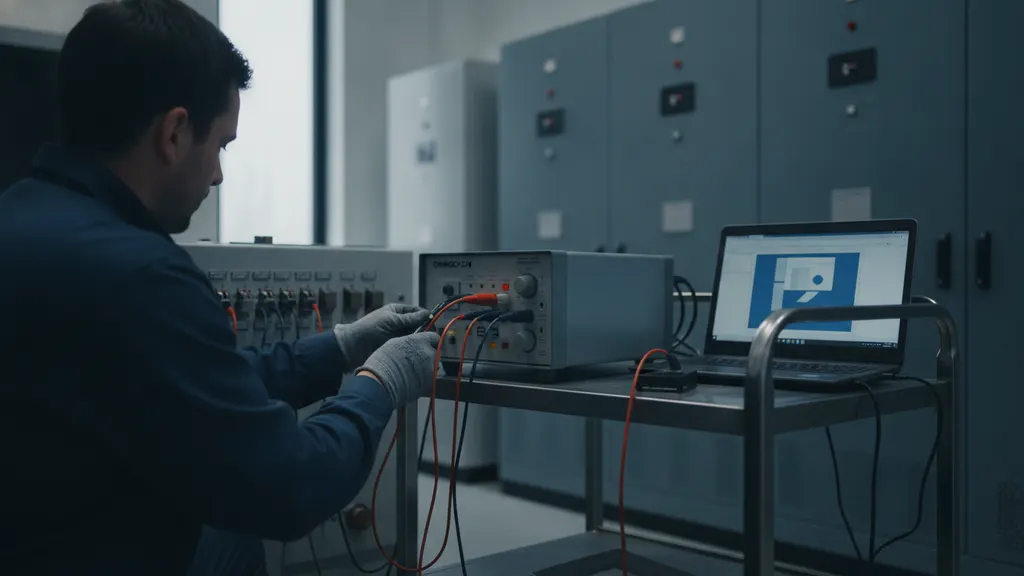
Effective protection relay testing solar substation configuration starts with the manufacturer settings file, a wiring drawing showing every terminal-block landing, and a bench-verified test set. OMICRON CMC 356 and comparable units deliver three-phase currents up to 32 A per phase and three-phase voltages up to 300 V, sourced from a vector-accurate signal generator.
Load the relay settings file into the test set’s configuration software before you land a single lead. Setting-group mirrors in the software auto-generate injection plans for every enabled element. Then land test leads at the relay’s isolation test switch, not upstream at the CT shorting block, so you never energize a live secondary loop by mistake.
Vector-accurate injection is the discriminator between modern amplified sets and legacy single-phase kits. A three-phase source lets you drive quadrature differential currents at exact phase angles, exercise polarizing quantities for directional overcurrent, and reproduce the sequence components a real fault would present. That capability is what enables full characteristic testing of distance, differential, and overcurrent elements in the field.
Time synchronization needs a plan too. IRIG-B or IEEE 1588 PTP from the substation clock keeps the test set’s timing reference aligned with SCADA event capture, so a 25 ms trip time you record on the test set matches the millisecond timestamp your gateway logs. See our IEEE 1588 PTP time sync guide for the wider substation clocking picture.
IEEE C37.233 acceptance criteria for pickup and trip time
IEEE C37.233-2009 defines the pass or fail thresholds utility reviewers apply to a protection relay testing solar substation report. Pickup for overcurrent, voltage, and frequency functions is generally accepted within plus or minus 3 to 5 percent of the configured setpoint, and trip times within plus or minus one cycle for instantaneous elements.
Curve-timed elements have their own rubric. For inverse-time overcurrent, the operating time at a specified multiple of pickup is checked against the published time-current characteristic, with a typical acceptance band of plus or minus 5 percent or 20 milliseconds, whichever is greater. Take measurements at three or more multiples of pickup, including one near the flat section of the curve and one near the definite-time region.
Differential functions require careful attention to slope and restraint. IEEE C37.233 recommends verifying the operating point at three or more restraint currents to build the actual operating characteristic, then confirming harmonic restraint at 2nd and 5th harmonic content typical of transformer inrush. Consult the IEEE C37.233 standard for the current published revision and errata.
NERC PRC-005-6 supplements the IEEE criteria with programmatic requirements. Every relay in a transmission protection system must have a documented maintenance interval, an owner-of-record, and a completed initial commissioning test on file. NREL’s utility-scale solar operations research highlights how commissioning-phase documentation gaps become long-tail O&M cost drivers.
Building the witness report utility protection engineers expect
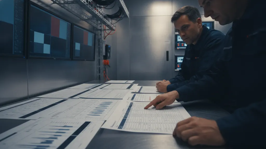
A witness-ready protection relay testing solar substation report ties every injected quantity to a relay setpoint and a signed acceptance decision. Utility protection engineers require the settings file version, CT and PT ratio evidence, test set model and calibration date, a pickup table, a trip-time table, timing oscillographs, and countersignatures from test engineer and reviewer.
Structure the report around the setting groups actually enabled in the relay. Reviewers cross-reference the acceptance decision line item against the setting group number and the ANSI device function to detect missing coverage. If Zone 2 distance is enabled in group 1 and it was not tested, that omission surfaces in the first 15 minutes of witness review. Across REIG’s 60-plus submitted witness packages, Zone 2 distance and 81-O overfrequency are the two most frequently skipped elements in first-draft reports, and both now appear in every pre-submission checklist we issue.
Include raw test-set files, not just PDF summaries. Modern test software emits an XML or COMTRADE record for every injection. Attach both the summary and the raw file so reviewers can re-plot your data if they want independent verification. During a utility witness review, the protection engineer typically imports COMTRADE records into a relay analysis tool, verifies that the injected phasors match the settings-file values, and confirms that each trip-contact closure time falls within the IEEE C37.233 acceptance band. A mismatch at that stage triggers a revision request, adding weeks to your commercial operation date. This one practice closes more revision cycles for protection relay testing solar substation teams than any other single step. Format the executive summary to answer three questions before the reviewer opens the appendix: did every enabled function pass, what was retested and why, and what is the calibration date and traceability of the test equipment. FERC large generator interconnection requirements specify documented commissioning evidence as a prerequisite for interconnection sign-off. For the wider commissioning package, see our companion piece on the solar SCADA witness pack and the DAS commissioning QA guide.
Frequently asked questions
How often does NERC PRC-005 require solar substation relay retesting?
NERC PRC-005-6 sets tiered maintenance intervals based on relay technology and monitoring level. Fully monitored microprocessor relays with self-diagnostics and communications supervision qualify for a 12-year maximum interval, while unmonitored microprocessor relays default to 6 years. Electromechanical and static designs carry shorter intervals. Solar plant owners typically inherit the transmission owner’s PRC-005-6 program at the point of interconnection. Read the current NERC PRC-005-6 reliability standard for the full table of intervals and the definition of monitoring attributes that qualify a relay for the longest interval band.
Is secondary injection alone sufficient, or do we still need a primary injection test?
Secondary injection verifies the relay’s logic, elements, and trip contacts, but it cannot prove the current transformer ratio, polarity, or accuracy under load. IEEE C37.233 and utility practice therefore require at least one primary injection or a CT ratio check per new CT circuit at commissioning. Once the CT circuit is proven, subsequent maintenance testing on the same relay can rely on secondary injection alone. For a full new substation build, teams primary-inject once, then use secondary injection for every element under that CT for the rest of the plant’s operating life, per EPRI power system protection research.
What test set specifications do most solar substation utilities accept for witness testing?
Utility acceptance typically requires a three-phase test set with vector-accurate current and voltage sources, calibration traceable to NIST, and a documented calibration date within the last 12 months. OMICRON CMC 356, Doble F6150SV, and Megger SMRT series all meet the technical bar for protection relay testing solar substation witness work. The NIST electrical standards program maintains the reference chain that flows through your calibration certificate. Include the certificate PDF in your witness package appendix and reference the traceability number in the executive summary so the reviewer can verify accuracy without hunting through appendices.
How do I coordinate secondary injection with SCADA event capture on a live substation network?
Coordinate through the substation gateway. Confirm the gateway is time-synchronized to the same reference as the test set, place the affected relay in test mode so its trip outputs do not operate primary breakers, and pre-brief the SCADA operator so injected alarms are documented as test events rather than real trips. IEC 61850 test-mode logic and DNP3 online-test flags both signal to the SCADA host that events are simulated. IEC 61850 defines the test-mode data model; see our GOOSE, MMS, and Sampled Values guide for the wider signaling picture.
What findings most often fail a protection relay testing solar substation witness review?
Reviewers report the same three findings across most protection relay testing solar substation projects: missing timing traces for one or more enabled elements, absent CT or PT ratio evidence, and settings files that do not match the version cited in the report. Signature omissions and calibration certificate lapses round out the top five. NERC audit findings on PRC-005 programs mirror these patterns in transmission audits. Build a pre-submission checklist that walks each of the top five failure modes and clears them before you hand the report to the utility.
How does secondary injection testing fit into a solar plant’s broader commissioning schedule?
Relay testing follows CT, PT, and DC circuit verification and precedes the utility witness energization walk. Plan for two to five days of testing per solar substation depending on relay count: a single-transformer 100 MW plant typically carries 12 to 18 protection relays, while a double-ended 200 MW site runs 25 to 32. Budget a day of report preparation per two days of testing. Sequence relay testing after grounding-system commissioning to an IEEE 80 baseline and before SCADA point-to-point verification. DOE-funded NREL utility-scale market research tracks how commissioning duration shapes project schedules and interconnection queue costs.