
Solar plant reactive power control: inverter VAR dispatch guide
Since FERC Order 827 took effect in June 2016, every new utility-scale solar interconnection must supply reactive power inside a ±0.95 power factor band at the high-side of the generator step-up transformer. Miss that window and the plant does not energize. Solar plant reactive power control VAR dispatch now sits at the intersection of inverter firmware, plant controller logic, SCADA telemetry, and transmission planner data submittals. This field guide walks power systems engineers through the standards, control modes, hardware, and test procedures needed for grid code compliance on utility-scale solar.
FERC Order 827 and solar plant reactive power control VAR dispatch requirements
In June 2016 FERC issued Order 827, which struck the prior exemption that let non-synchronous generators skip reactive capability testing. Every new interconnection agreement now requires utility-scale solar and wind plants to supply reactive power inside a ±0.95 power factor band at the high-side terminals of the generator step-up transformer, measured at full nameplate active output. This changed the baseline for solar plant reactive power control VAR dispatch design across every North American ISO.
Reactive capability at partial P output is prorated per the plant approved P-Q or D-curve. The transmission operator interconnection studies use this envelope to size local voltage support and to model contingency reactive reserves. Missing the ±0.95 target at the point of interconnection cannot be papered over with fixed shunt capacitors alone. See the companion IEEE 1547 voltage ride-through guide for how these envelopes interact with fault-ride-through requirements.
Order 827 also directs that the plant demonstrate capability rather than only install rated equipment. That has downstream effects on inverter procurement, auxiliary loss budgets, and MV collector cable sizing. Because inverter reactive capacity shrinks as active power output rises, plants sometimes de-rate a few inverters or add active compensation to hold the band across the full P sweep.
For a closer look at this, see Solar plant transformer DGA: dissolved gas analysis field guide.
For a closer look at this, see Solar Curtailment and AGC in Utility-Scale Solar Plant Operations.
For a closer look at this, see Solar plant frequency response: FFR and synthetic inertia guide.
For a closer look at this, see Solar plant AC grounding and ground grid design: IEEE 80 field guide.
Inverter modes for solar plant reactive power control VAR dispatch
Modern PV inverters ship with several Q control modes, each mapping to a different grid operator preference. IEEE 1547-2018 Section 7 formalized these functions and requires that every inverter rated over 500 VA expose them through a documented protocol interface. The three commonly deployed modes for solar plant reactive power control VAR dispatch are fixed power factor, voltage regulation, and Q(V) droop.
Fixed power factor mode holds a constant PF such as 0.95 leading or lagging regardless of grid voltage. It is common where the interconnection agreement writes a static PF setpoint. It is dispatchable from the plant controller but does not react to local voltage changes on its own.
Voltage regulation mode drives Q output to hold a target voltage at a defined regulation point. Plants on weak feeders often run this mode, but it can hunt against upstream regulators if the deadband and time constants are not tuned against the transformer LTC bandwidth.
Q(V) droop is the IEEE 1547 default: Q output changes linearly with voltage deviation, with configurable deadband and slope. On utility-scale plants it typically runs at the inverter for fast local response while the plant controller trims aggregate setpoints. NREL field research on advanced inverter functions shows Q(V) droop reduces voltage excursions on high-penetration feeders without measurable curtailment.
| Mode | Response layer | Best fit |
|---|---|---|
| Fixed PF | Inverter, static | Fixed PF setpoint per agreement |
| Voltage regulation | Inverter closed loop | Sole voltage source on a feeder |
| Q(V) droop | Inverter autonomous | High-penetration feeder support |

SCADA integration for solar plant reactive power control VAR dispatch setpoints
The power plant controller (PPC) acts as the aggregation layer for solar plant reactive power control VAR dispatch, sitting between the utility SCADA automatic voltage regulator setpoint and the fleet of inverters. Setpoints arrive over DNP3 or IEC 61850 typically at 1 to 4 second update rates, and the PPC resolves them into per-inverter Q or PF commands that respect each unit capability curve and MV collector limits.
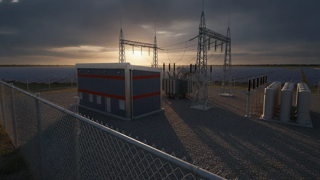
Cascaded loop design matters. A fast inner loop at the inverter (10 to 100 ms) handles ride-through and local voltage response. The plant loop (0.5 to 2 seconds) trims the aggregate against the utility target. This decoupling avoids the classic ping-pong instability that appears when both layers try to close on the same variable at similar time constants. Our power plant controller SCADA integration guide covers PPC tag map design in more depth.
Solar plant reactive power control VAR dispatch has to account for auxiliary reactive losses in the collector system and the generator step-up transformer. Because the ±0.95 measurement point is at the high-side of the GSU, inverters at the far end of a 34.5 kV feeder often need to run past their nameplate PF just to compensate for line losses. Model the collector Q losses in PSS/E or PSCAD before you commit inverter Q capability to a transmission planner.
Curtailment mode interacts directly with Q dispatch. When the utility issues an active power curtailment, inverter Q capability grows because apparent power headroom opens. Well-designed PPCs recompute the Q setpoint on the fly. The solar curtailment and AGC guide walks through the coordinated dispatch logic. EPRI research on PPC tuning documents typical latency budgets from utility setpoint issue to inverter Q change.
For a closer look at this, see How solar SCADA reduces unplanned downtime at utility-scale plants.
For a closer look at this, see Solar plant SCADA system modernization: a utility upgrade roadmap.
For a closer look at this, see Solar Power Plant Controller: SCADA Integration, Setpoints, Limits.
Sizing STATCOM and SVC for utility-scale solar farms
When inverter Q capability plus fixed compensation cannot cover the interconnection envelope across all operating states, a active reactive device is required. STATCOM is now more common than the classic SVC on new solar farms because it holds Q output down to roughly 15 percent of rated voltage during faults, matching the ride-through profile IEEE 1547-2018 demands. SVCs, by contrast, lose Q output as V² and become passive during deep sags.
Sizing follows a deficit study across the P-Q envelope. Map inverter Q capability at 0, 25, 50, 75, and 100 percent P output. Subtract collector and transformer Q losses. Compare against the ±0.95 PF requirement at the point of interconnection across the full P sweep. The largest deficit sets the STATCOM MVAr rating. Add a margin for one-inverter contingency if the interconnection agreement includes an N-1 requirement.
STATCOMs on utility-scale solar typically fall in the 15 to 75 MVAr per unit range, with modular multilevel converter topologies dominating above 30 MVAr. Placement matters. Locating the STATCOM at the collector substation MV bus keeps the reactive current out of the collector cables and reduces I²R losses across the fleet. This is where solar plant reactive power control VAR dispatch design pays for itself in reduced O&M costs across the plant life.
NERC MOD-025-2 verification for solar plant reactive power control VAR dispatch
NERC MOD-025-2 requires plant owners to verify real and reactive capability in the field and submit updated data to the transmission planner every 5 years, or after any modification that could change capability. Witness testing steps the plant through the P-Q envelope while an authorized witness records terminal voltage, active power, reactive power, and setpoint tracking.
The test sequence is scripted before commissioning. A typical run steps through 100 percent P at 0.95 lag, 100 percent P at 0.95 lead, 50 percent P at capability limits, and 0 percent P at night mode Q. Any inverter that trips, any breaker that opens, or any voltage excursion outside the interconnection limits invalidates the run. Keep a backup script for cloud transient recovery so the crew can resume without losing the witness slot. Our SCADA commissioning witness pack guide covers the documentation package.
Data submission format follows the transmission planner template. Most planners now accept CSV plus a PDF single-line and P-Q chart, but the utility should confirm before test day. Include instrument transformer accuracy class and PT/CT ratios in the submittal. DOE grid modernization research flags data quality as a common cause of resubmission cycles.
Frequently asked questions
What did FERC Order 827 change for utility-scale solar reactive power?
FERC Order 827, issued in June 2016, removed the prior exemption that let non-synchronous generators skip reactive capability requirements. Since then, every new interconnection agreement for utility-scale solar has required the plant to supply reactive power inside a ±0.95 power factor band at the high-side of the generator step-up transformer at full nameplate active output. The order applies to the interconnection point rather than individual inverters, so plants can meet the requirement through a mix of inverter Q capability, fixed compensation, and active devices such as STATCOMs. See FERC Order 827 for the full rule text and background.
When should a solar plant run fixed power factor instead of Q(V) droop?
Fixed power factor mode fits interconnection agreements that write a static PF setpoint and where the utility does not need active voltage support from the plant. It is simple to dispatch, straightforward to audit during NERC MOD-025-2 testing, and it avoids interaction with upstream LTC controls. Q(V) droop is preferred on high-penetration feeders where local voltage response matters more than a fixed PF. On many utility-scale plants both modes live in the inverter firmware, with the plant controller switching between them based on the utility SCADA command received that hour.
Do all utility-scale inverters support IEEE 1547-2018 volt-var functions?
Every inverter certified after the IEEE 1547-2018 revision is required to expose the volt-var, watt-var, volt-watt, and freq-watt functions listed in Section 7. Older 1547-2003 inverters may still be in service and typically require firmware upgrade or replacement to comply with newer interconnection agreements. Confirm certification against UL 1741 SB before procurement, and check that the inverter documentation lists the exact function IDs and default parameters. Some vendors also gate advanced functions behind license keys that must be enabled during commissioning.
How often does NERC MOD-025-2 field verification need to happen?
NERC MOD-025-2 requires reactive and real power capability verification and data resubmission at least every 5 years, and after any modification that materially changes plant capability. Common triggering modifications include inverter firmware upgrades that change Q limits, addition or removal of a STATCOM, GSU replacement, and collector expansion. The witness test itself typically runs 4 to 8 hours on a clear day and requires coordination with the balancing authority for the P-Q envelope excursions. Data is submitted to the transmission planner in the planner specified format, usually CSV plus PDF chart.
When does a solar farm require a STATCOM instead of relying on inverters alone?
A STATCOM is required when a deficit study across the P-Q envelope shows that inverter Q capability plus any fixed shunt compensation cannot hold the ±0.95 power factor band at the point of interconnection at every P output. Common causes include long MV collector runs with high Q losses, high inverter loading factors that leave little apparent power headroom for Q, and interconnection agreements with stricter voltage support requirements than the 1547 default. STATCOMs also hold Q down to roughly 15 percent voltage during faults, which fixed capacitors cannot. Solar plant reactive power control VAR dispatch design should test the STATCOM decision early in the study phase.
What SCADA update rate is typical for VAR dispatch setpoints?
Utility SCADA systems typically send Q or voltage setpoints to the plant controller at a 1 to 4 second cadence over DNP3 or IEC 61850 MMS. The plant controller then resolves the setpoint into per-inverter Q or PF commands at a 200 ms to 1 second cadence, and the inverter internal Q loop closes at 10 to 100 ms. Solar plant reactive power control VAR dispatch relies on this cascade of response times to keep the plant stable across grid disturbances while still tracking the utility target within one AGC cycle. EPRI grid integration research documents typical latency budgets for these three layers.