


Solar Power Plant Controller: SCADA Integration, Setpoints, Limits
The solar power plant controller (PPC) is the central brain that translates grid operator commands into coordinated action across inverters, transformers, and reactive devices. On a 100 MW PV site, a half-second delay in PPC setpoint dispatch can mean the difference between meeting interconnection ride-through and tripping the point of interconnection. This article walks through the SCADA architecture, setpoint hierarchy, and plant limit logic that production engineers actually wire and tune.
What a solar power plant controller does
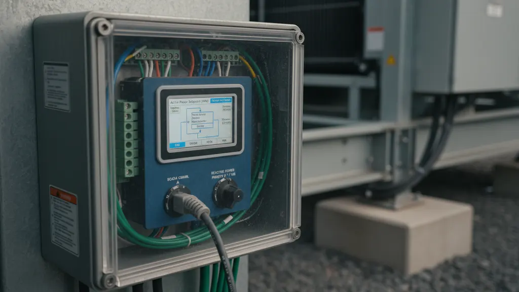
A solar power plant controller orchestrates every grid-facing function the site exposes to the utility. Inverters can island, but they cannot self-coordinate to maintain a 0.95 power factor at the point of interconnection or to ride through a 150 ms voltage dip with synchronized reactive injection. The PPC closes that loop.
The controller subscribes to two command streams: utility dispatch (active power, reactive power or voltage setpoint, ramp rate, emergency curtail) and plant operator overrides (maintenance lockout, weather curtail, IGS islanding). It publishes aggregated plant state back to SCADA on the same cycle: generation, available power, fault accumulators, and the active dispatch mode.
In a typical US interconnection, the IEEE 1547-2018 grid integration standard defines the response time requirements that drive PPC architecture decisions. The NREL plant controller reference architecture documents the minimum function set: P/Q control, voltage support, frequency response, and ride-through coordination.
Modern PPC platforms (vendor implementations from GE, Emerson Ovation, AGS) all share the same primitive: arbitrate the dispatch hierarchy, push setpoints to every inverter on the same scan, and confirm the response before the next utility poll. Anything slower than 250 ms round-trip on reactive power will fail most interconnection studies under current grid codes.
For a closer look at this, see Solar Curtailment and AGC in Utility-Scale Solar Plant Operations.
SCADA integration architecture for the solar power plant controller
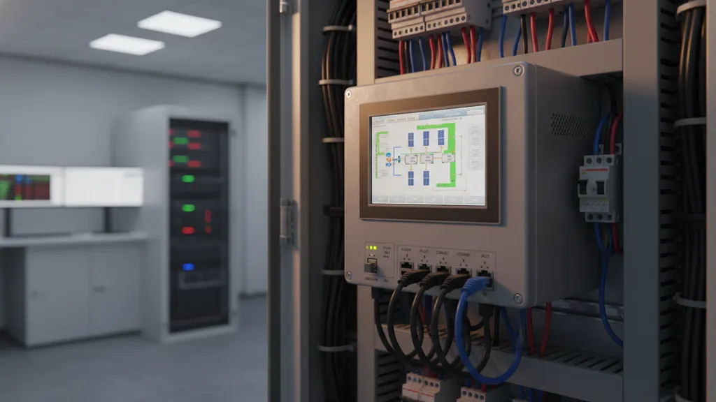
SCADA integration is where the solar power plant controller earns or loses its commissioning sign-off. The PPC sits on an isolated control VLAN, separated from corporate IT via a NIST SP 800-82r3 industrial firewall, and exposes three discrete interfaces:
| Interface | Protocol | Poll rate | Purpose |
|---|---|---|---|
| North: Utility ICCP | IEC 60870-6 / DNP3 over routed VPN | 2 to 4 s | Dispatch setpoints from RTO / ISO |
| West: Plant SCADA | OPC UA, Modbus TCP | 1 to 2 s | HMI tags, alarms, trends |
| South: Field devices | Modbus TCP, EtherCAT, IEC 61850 GOOSE | 100 to 500 ms | Inverters, met stations, reactive devices |
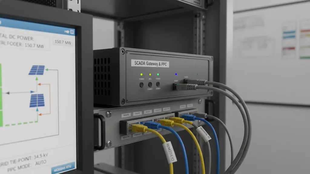
The southbound link is where the controller actually does work. A 200 MW plant might host 80 to 120 string inverters; the PPC writes a single per-inverter active power setpoint each scan, then verifies the aggregated response against the dispatch target. The ISA-95 functional hierarchy places the PPC at Level 2, with SCADA at Level 3 and utility ICCP at Level 4.
Time synchronization matters here. PTP (IEEE 1588) holds the PPC and every inverter to within 1 ms, the minimum needed to timestamp ride-through events for NERC PRC-024-3 compliance reporting. Plants that rely on NTP lose the ability to reconstruct fault sequences during interconnection disputes.
Most plant SCADA gateways front the PPC Modbus or OPC UA registers, then republish to the historian and the HMI. The pattern we recommend on commissioning is to expose the controller internal setpoint hierarchy as separate tags so O&M teams can see which mode is active without diving into the vendor HMI.
For a closer look at this, see Solar SCADA commissioning: building the utility witness pack.
For a closer look at this, see Solar SCADA Alarm Rules: Cut Nuisance Noise on Utility-Scale Plants.
For a closer look at this, see Solar plant SCADA system modernization: a utility upgrade roadmap.
For a closer look at this, see Solar tracker SCADA integration: backtracking and tag map design.
For a closer look at this, see How solar SCADA reduces unplanned downtime at utility-scale plants.
For a closer look at this, see Modbus TCP vs DNP3: solar SCADA protocol guide for utility plants.
We cover the details separately in Solar SCADA Failover Architecture for High Availability Plants.
For a closer look at this, see Utility Scale Solar Monitoring vs SCADA: Roles and Layers Defined.
For a closer look at this, see Solar SCADA cybersecurity NERC CIP: utility-scale compliance guide.
There is a full breakdown of this topic in BESS SCADA Integration for Utility-Scale Solar Plants: A Field Guide.
We cover the details separately in IEEE 1588 PTP Time Sync for Solar SCADA: GPS Clock Field Guide.
Setpoints and reference signals the PPC manages
Setpoints are the active dialogue between the grid operator and the plant. The PPC manages four primary references on a continuous loop:
- Active power (P) from utility dispatch or weather curtail, in MW
- Reactive power (Q) or power factor as either a signed MVAR setpoint or a target PF
- Voltage (V) regulating the POI to a scheduled per-unit value
- Frequency response with droop curves engaged during off-nominal events
A well-tuned solar power plant controller picks one P-mode and one Q-mode at any instant. Mode conflicts (utility commanding fixed PF while plant is in voltage regulation) are the single most common cause of unintended curtailment. The EPRI Plant Controller Tuning Guidelines recommend a hard interlock that publishes the active mode to SCADA every scan.
Inverter-level setpoints derive from plant-level targets through a distribution algorithm. Two common methods:
- Equal-share: each inverter gets the plant target divided by count
- Proportional: each inverter is allocated by available power, respecting clipped strings and shaded panels
Proportional dispatch is the default on most utility-scale solar sites because it minimizes wear on individual inverters and keeps available-power margin closer to actual capability. See our writeup of DAS data acquisition systems for solar plants for how the available-power calculation feeds the controller.
The setpoint loop closes through a deadband. A 1% voltage deadband around the reference prevents the PPC from hunting on a windy day when irradiance is bouncing. Tuning that deadband during commissioning separates a stable plant from one the ISO ramps off the grid for control instability.
Plant limits and curtailment logic
Plant limits are the safety net the PPC enforces regardless of dispatch commands. Five categories appear in every interconnection agreement filed with FERC under the Standard Large Generator Interconnection Agreement:
- Maximum active power (typically the nameplate MW rating)
- Maximum and minimum reactive power (the D-curve, bounded by inverter MVAR capability and transformer tap range)
- Maximum ramp rate up and down (often 10% per minute, set by interconnection study)
- POI voltage envelope (typically 0.95 to 1.05 per unit)
- Frequency response curves (droop, deadband, response time)
Curtailment is the most operationally visible plant limit. The solar power plant controller receives a curtailment command from the utility (or from the plant operator for maintenance) and reduces output by ramping inverters at the contracted rate. The hard part is graceful return: when the curtail signal releases, the PPC must ramp back without overshoot, or it triggers a coordinated under-frequency penalty under the generator owner / operator agreement.
The DOE Solar Energy Technologies Office grid integration research documents how curtailment frequency has grown roughly fourfold across the western interconnection between 2019 and 2024. That growth makes curtailment logic the highest-impact PPC tuning target on most newer plants.
A practical safeguard: program the PPC to enter a fixed PF mode if it loses ICCP communication with the utility for more than 30 seconds. Without that safeguard, a comms outage during a voltage event can pull the plant into uncoordinated reactive support that the ISO will penalize.
Commissioning and tuning a solar power plant controller
Commissioning a solar power plant controller is a staged process tied to plant energization, not a single test day. The sequence we run on every utility-scale site has six gates:
- PPC offline FAT (factory acceptance) with simulated I/O, all logic blocks proven against the design spec
- SAT on plant LAN where the PPC reads every inverter and writes a 1% setpoint without grid connection
- First sync at 10% available power with utility witnessing dispatch response on P and Q
- Mid-irradiance test at 50% available where ramp rate, voltage regulation, and deadband behavior get tuned
- Full output test at 90%+ available exercising all modes and ride-through simulation per IEEE 2800-2022 for inverter-based resources
- 30-day surveillance run with grid operator dashboard access
Tuning happens mostly in gates 4 and 5. The PI gains on the voltage regulator and the reactive power controller are the two parameters that most affect plant stability. Set the integral term too aggressive and the PPC hunts; too conservative and it never reaches the voltage target on a slow ramp.
The SEIA utility-scale interconnection guidance catalogs escalation paths when the PPC fails to meet interconnection performance during witness tests. The most common cause we observe is inverter response time mismatch: the controller assumes a 100 ms inverter acknowledgment, the field reality is 400 ms, and the PI loop oscillates.
Document every gain change in the PPC commissioning log and tag it in SCADA. Post-event analysis depends on reconstructing the gains the controller was running. Our checklist for inverter commissioning best practices pairs with PPC tuning on the inverter side.
Common failure modes and PPC troubleshooting
Three failure modes account for most PPC-related incidents we see across the fleet.
Mode A: setpoint distribution drift. The plant target is met but individual inverters carry disproportionate load. Root cause is usually a stale available-power calculation in the DAS feed. The fix is validating the DAS poll cycle against the PPC scan rate. Mode A failures rarely originate in the solar power plant controller itself; they trace back to the DAS feed.
Mode B: reactive power mode conflict. Utility commands fixed PF, plant SCADA forces voltage regulation, the PPC arbitrates incorrectly and lands at the wrong reference. The fix is the SCADA tag interlock from the setpoints section plus an alarm that prevents two Q-modes from being active.
Mode C: comms loss orphan. The PPC loses ICCP, continues issuing setpoints to inverters, and drifts the POI voltage outside envelope. The fix is the 30-second comms-loss safeguard. See OSHA electrical safety standards for the work-permit framework that governs PPC troubleshooting during energization.
The diagnostic workflow we standardize on every new site appears in our writeup of SCADA monitoring for utility-scale solar. Field engineers should pull the controller internal log, the SCADA historian, and the inverter event log onto a single timeline before forming a hypothesis.
Frequently asked questions
What is a solar power plant controller and where does it sit in the SCADA stack?
A solar power plant controller is the dedicated industrial controller that coordinates every grid-facing function across inverters, transformers, and reactive devices on a utility-scale PV site. It sits between the utility dispatch interface (ICCP at Level 4 of the ISA-95 hierarchy) and the field devices at Level 1 and 2. The PPC translates grid operator setpoints into per-inverter commands, enforces interconnection limits, and reports aggregated plant state back to SCADA. On most modern US plants, the PPC operates as a separate physical platform from the plant SCADA gateway, isolated on its own control VLAN per NIST SP 800-82r3 industrial control guidance.
How does the PPC communicate with inverters and meters?
The southbound interface from the PPC to inverters and meters typically uses Modbus TCP, with EtherCAT or IEC 61850 GOOSE on newer inverter-based resource builds. Poll rates run 100 to 500 ms per device, which is fast enough to support voltage regulation and reactive power control loops within the interconnection performance window. PTP (IEEE 1588) holds all devices to within 1 ms of plant time, required to timestamp ride-through events for NERC PRC-024-3 reporting. The IEEE 2800-2022 standard for inverter-based resources defines the minimum performance the inverters must expose to the solar power plant controller.
What setpoints does a PPC manage and which mode wins when they conflict?
A PPC manages four reference signals on a continuous loop: active power, reactive power (or power factor), voltage, and frequency response. At any instant, exactly one P-mode and one Q-mode are active. The dispatch hierarchy is set during commissioning and published to SCADA every scan: utility ICCP dispatch usually overrides plant-local setpoints, with operator manual override reserved for maintenance and emergency cases. Mode conflicts (utility commanding PF while plant SCADA forces voltage regulation) are the most common cause of unintended curtailment, per EPRI plant controller tuning research and NREL field surveys.
How often should PPC tuning be revisited after the plant is energized?
Plant operators should review PPC tuning at least annually and after any change to the interconnection topology, inverter firmware, or reactive device configuration. Voltage regulator and reactive power PI gains drift in relevance as inverter populations age and string availability shifts. Per EPRI Plant Controller Tuning Guidelines, a quarterly review of curtailment frequency and POI voltage excursion logs flags tuning drift before it becomes an interconnection performance issue. Document every gain change in the commissioning log and tag it in SCADA so post-event analysis can reconstruct the controller state.


