Solar substation transformer differential protection: IEEE C37.91 guide
NERC’s 2022 State of Reliability report flagged protection system misoperations as a repeat contributor to bulk-system disturbances, and transformer relays sit at the top of that list. Solar substation transformer differential protection is the closest defense a step-up bank has against faulted windings, and its slope, pickup, and harmonic settings decide whether a real fault clears in three cycles or a nuisance trip parks a 200 MW plant during peak dispatch.
Why solar substation transformer differential protection is design-critical for utility-scale generation
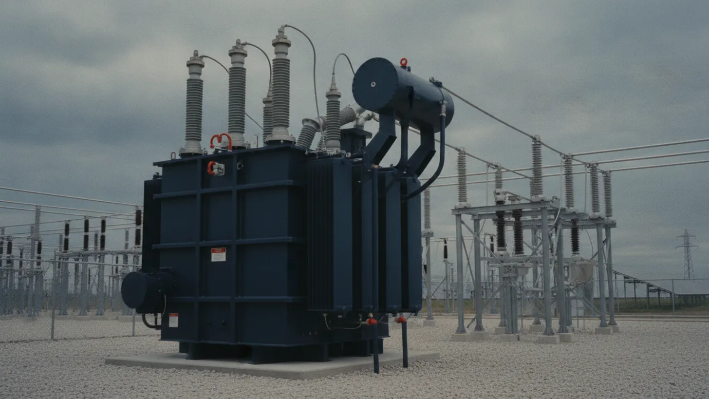
Solar substation transformer differential protection guards the generator step-up transformer that ties the medium-voltage collection system to the transmission grid. A stuck or delayed trip on a phase-to-ground fault inside the tank means burnt copper, cracked porcelain, and a replacement lead time measured in months. On a 100 MW block, that is production loss the PPA does not forgive.
The step-up bank sits between the inverter yard and the point of interconnection, and it runs duty cycles utility grid transformers were not always designed for. Repeated ramping, curtailment events, and reactive absorption push winding stress higher than a fossil generator would see. Per the North American Electric Reliability Corporation, protection misoperations were a repeat driver of major event days across the bulk system in 2022, and inverter-based resources amplify that pressure because clearing time is measured against grid-code ride-through windows.
Backup schemes like sudden-pressure relays and Buchholz devices exist, but they act on secondary evidence and rarely operate fast enough to save a winding on an internal phase-to-phase fault. That leaves solar substation transformer differential protection as the primary high-speed element, and IEEE C37.91-2008 is the document that governs how the relay is applied. Companion schemes like GOOSE-based protection messaging handle interlock and trip transfer to the collection breakers.
For a closer look at this, see Solar plant AC grounding and ground grid design: IEEE 80 field guide.
We cover the details separately in Solar substation IEC 61850 GOOSE messaging: relay protection guide.
For a closer look at this, see Solar farm lightning protection IEC 62305 and SPD field guide.
For a closer look at this, see IEC 61850 Solar Substation: GOOSE, MMS, and Sampled Values Guide.
For a closer look at this, see Solar plant transformer DGA: dissolved gas analysis field guide.
Selecting slope and pickup for solar substation transformer differential protection per IEEE C37.91
IEEE C37.91-2008 recommends a dual-slope characteristic, with a low-slope segment near 20 to 30 percent from zero to the knee and a high-slope segment of 60 to 80 percent above it. Pickup sits around 20 to 30 percent of tap. Those values give sensitivity to internal faults while riding through CT saturation and tap-changer mismatch.
The IEEE Standards Association publishes C37.91 as the guide for transformer protection, and it lays out the reasoning behind the dual-slope. Slope 1 has to see internal faults small enough to matter but ignore normal mismatch from tap changers and CT accuracy class. Slope 2 has to swing the operating characteristic away from the origin fast, so a CT that saturates on an external fault does not push false differential current into the operate region.
On a solar step-up bank at 34.5 kV to 230 kV, mismatch sources add up: on-load tap changer at plus/minus 10 percent, CT ratio error at 5 to 10 percent depending on class, and small vector-group compensation residuals. Setting slope 1 too low risks a nuisance trip on load; setting it too high blinds the relay to low-magnitude turn-to-turn faults. Most solar substation transformer differential protection schemes land at 25 to 30 percent slope 1 and 70 percent slope 2 with a 2 x pickup knee. That leaves margin for the tap changer to walk without operating.
For a closer look at this, see IEEE 1588 PTP Time Sync for Solar SCADA: GPS Clock Field Guide.
For a closer look at this, see Solar farm arc flash analysis NFPA 70E: IEEE 1584 and PPE guide.
Harmonic restraint in solar substation transformer differential protection during energization
Second-harmonic restraint set at 15 to 20 percent of the fundamental blocks the differential element during magnetizing inrush, which can reach 8 to 12 times rated current on a cold energization. Fifth-harmonic restraint at 25 to 35 percent blocks on overexcitation. Both are standard practice under IEEE C37.91.
When a transformer energizes into a de-fluxed core, the inrush current is asymmetrical, offset, and rich in second harmonic. A relay that only measured fundamental differential would see hundreds of amps of apparent internal current and trip within a cycle. Second-harmonic restraint compares the second-harmonic component of the differential current to the fundamental and blocks the operate signal when the ratio exceeds the setting, usually 15 to 20 percent.
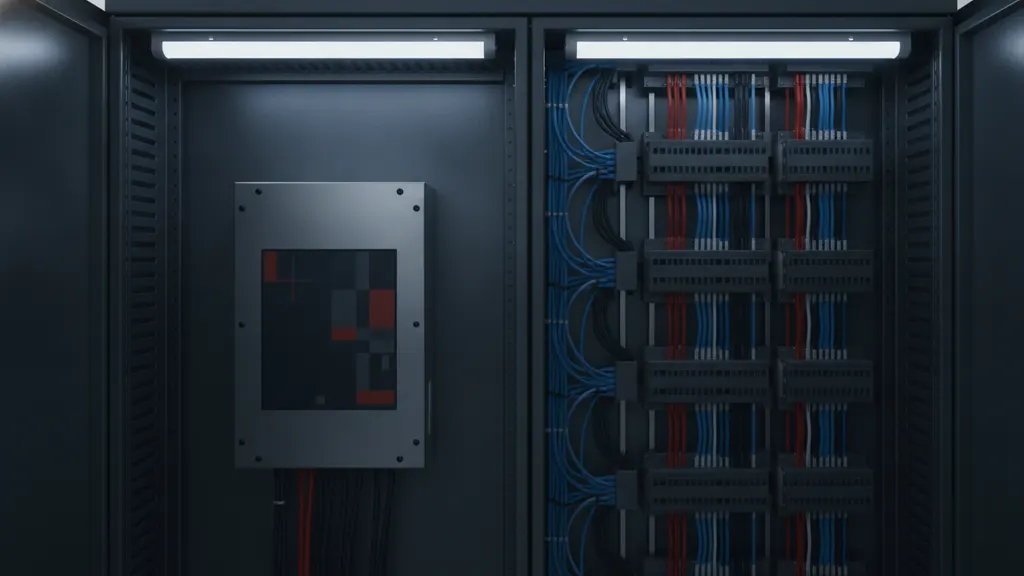
Modern relays offer per-phase restraint, cross-phase blocking, or waveform-based inrush detection. Per-phase blocking is the safest starting point on a solar substation transformer differential protection scheme, because inverter-based collection systems can produce phase-imbalanced inrush profiles that confuse cross-phase logic. The Electric Power Research Institute has published field data showing that residual-flux-dependent inrush on repeat re-energizations trips schemes that were tuned only for cold starts, so the harmonic block has to hold on the second and third attempts too.
Fifth-harmonic restraint handles a different failure mode. Overexcitation from grid overvoltage or under-frequency drives the core into saturation on the positive half-cycle only, producing a differential signature dominated by fifth harmonic. Blocking at 25 to 35 percent stops the relay from acting on an overexcitation condition that a volts-per-hertz element should handle instead.
CT ratio correction and winding compensation for solar substation transformer differential protection
On a numerical relay, CT ratio mismatch and vector-group phase shift are corrected inside the settings file, not with interposing CTs. The relay reads primary CT ratio for each winding, applies matrix compensation for the vector group (typically YNd11 or Dyn1 on a solar step-up), and produces per-unit currents that the differential element compares directly.
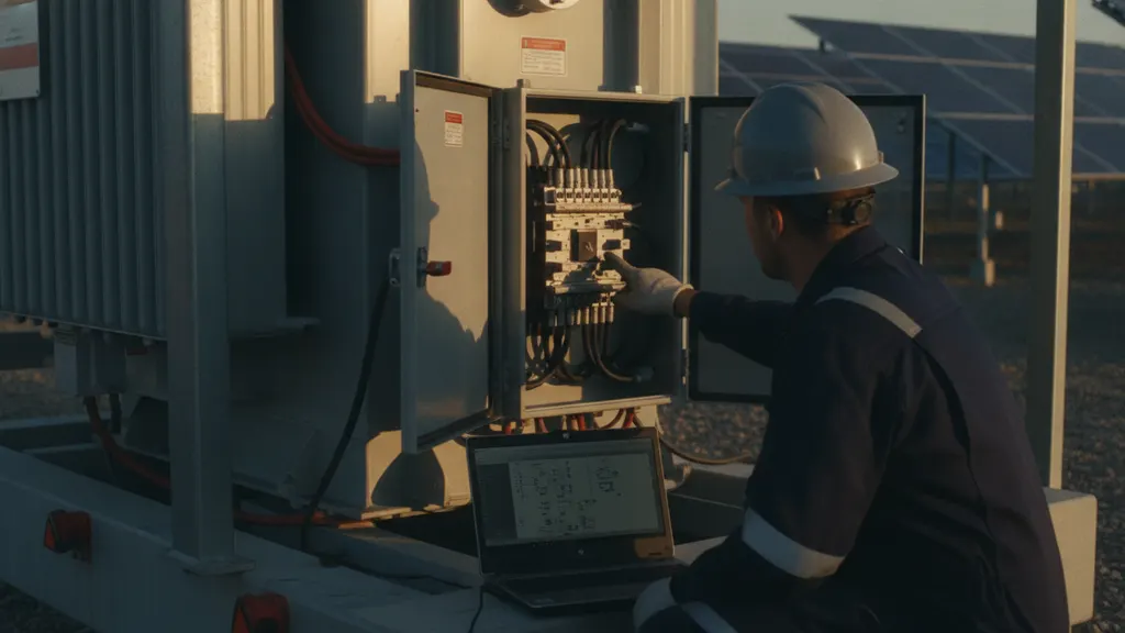
On the HV side of a 230 kV step-up, CT ratios of 1200:5 or 2000:5 are common; on the 34.5 kV LV side, ratios can run 3000:5 or higher. Historic electromechanical schemes had to match those with auxiliary CTs and specific tap positions on the relay. That is no longer the case. Every major numerical relay platform accepts primary CT ratio in the settings and computes the compensation factor internally.
Vector-group compensation is the second half. A YNd1 transformer has a 30-degree phase shift between HV and LV; the relay has to rotate the LV currents by 30 degrees before differencing. Standard vector groups (Yy0, Yd1, Dy11, YNd1) are pre-programmed on most relays. Zero-sequence current elimination on the wye-connected side is also required, otherwise external ground faults on the wye side will produce false differential current. The IEC vector-group table is the reference for the rotation matrix.
A specific trap on solar substation transformer differential protection schemes: the neutral CT on the wye-connected HV winding is often installed for restricted earth-fault (REF) protection but wired backwards. If REF is enabled without confirming CT polarity against the phase CTs, the ground-fault element mistrips on load. At a 120 MW project in the Carolinas, a reversed LV neutral CT polarity found on first bench test would have caused REF mistrip on the initial load ramp had the wiring gone unchecked. Bench-verify polarity with a battery test before energization, and cross-check that the neutral CT is tied to the same ground bus described in the IEEE 80 substation ground-grid design.
Secondary injection testing to verify solar substation transformer differential protection settings
Secondary injection with a three-phase test set (Omicron CMC 356 or Doble F6350 class) is the required verification step before energization. Inject balanced load current to confirm zero differential, apply a simulated internal fault to verify slope pickup, then inject second harmonic to confirm the block. Timing tests confirm trip time under 30 milliseconds at 2 x pickup.
The commissioning script for solar substation transformer differential protection follows a fixed sequence. First, in-service balance: inject rated secondary current in both windings with correct vector rotation and confirm the relay reads near-zero differential (under 5 percent is a healthy target). Second, slope test: sweep restraint current from 0.5 to 5 x pickup at increasing differential and record the pickup boundary. Slope 1 and slope 2 should match the settings file within 5 percent.
Third, harmonic block: inject fundamental plus second harmonic at rising ratio and confirm the block engages at the set percentage. Fourth, timing: at 2 x pickup, the trip contact should close within 20 to 30 milliseconds on modern numerical relays. Fifth, direct transfer trip and lockout: confirm the 86 lockout coordinates with the breaker-fail scheme and the SCADA alarm reports the operation on the correct point. The U.S. Department of Energy commissioning guides for large generation substations call out the injection sequence explicitly, and the utility witness pack should record every stage for turnover.
The final step is a live-load balance recheck after energization. Once the transformer is carrying load, the differential reading should stay under 5 percent through the day’s ramp. A drift above that value is the earliest warning that something is off, and it should trigger a de-energization and CT-circuit inspection before the plant runs another shift. Log the injection values, the live-load reading, and the settings file signature in the commissioning package that ships to the utility.
| Setting | IEEE C37.91 target range | Typical solar step-up value |
|---|---|---|
| Slope 1 | 20 to 30 percent | 25 percent |
| Slope 2 | 60 to 80 percent | 70 percent |
| Knee current | 1.5 to 3 x rated | 2 x rated |
| Second-harmonic block | 15 to 20 percent | 17 percent |
| Fifth-harmonic block | 25 to 35 percent | 30 percent |
| Trip time at 2 x pickup | Under 30 ms | 20 to 25 ms |
For a closer look at this, see Protection relay testing solar substation secondary injection guide.
Frequently asked questions
What does IEEE C37.91 actually cover for solar substation transformer differential protection?
IEEE C37.91-2008 is the guide for protective relay applications on power transformers and covers differential, restricted earth fault, overcurrent backup, overexcitation, and thermal protection. For solar step-up banks, the differential and REF sections are the two most-cited. The standard gives recommended slope ranges, harmonic restraint values, and CT selection guidance that most utility interconnection agreements reference directly. It is republished periodically by the IEEE Power and Energy Society, and any commissioning package for a generation substation should include a copy alongside the manufacturer relay manual. Deviations from C37.91 must be documented in the settings basis.
Why is second-harmonic restraint set at 15 to 20 percent and not lower?
Second-harmonic content in transformer inrush current is high on a cold energization, often 40 to 60 percent of the fundamental. Setting the block at 15 to 20 percent gives margin above the highest second-harmonic content that a real internal fault would produce, which is typically under 10 percent. If the block is set below 10 percent, the relay can hold during a real fault, delaying the trip. If it is set above 25 percent, the block may release during a warm re-energization when second-harmonic content decays faster than expected. The 15 to 20 percent window is the practical compromise per EPRI field data.
How does inverter-based generation change the fault current signature the relay sees?
Inverter-based resources produce fault current at 1.1 to 1.5 times rated instead of the 5 to 10 times a synchronous generator would deliver. That means the ground-fault signature on the LV side of the step-up is smaller and shorter than the relay was originally designed to see. Differential protection is not directly affected, because it measures the difference between windings, not the absolute magnitude of infeed. But backup overcurrent coordination, breaker-fail timing, and REF sensitivity all need to be reviewed against the inverter fault-contribution profile. On a 200 MW solar block where inverter fault contribution holds at 1.2 times rated for roughly 100 milliseconds before current limiting kicks in, a standard 50-millisecond breaker-fail timer coordinated for synchronous infeed may not give the backup element enough time to assert. NERC reliability standard PRC-019-2 addresses coordination between generation protection and capability, and PRC-024-2 covers relay settings relative to voltage and frequency ride-through windows. Both apply when any relay element’s pickup or timing is set for a fault profile that inverter controls can no longer sustain.
Can I use a single-slope characteristic instead of dual-slope for a solar step-up?
Single-slope was standard on older electromechanical relays, and it still works, but modern numerical relays offer dual-slope for a reason. On an external fault where one CT saturates and the other does not, the false differential current can climb into the operate region of a flat 30 percent slope. A dual-slope with a knee at 2 x rated pushes the operate boundary out of reach of realistic saturation-driven differential. For a utility-scale solar plant with 200 kA available fault current on the HV side, use dual-slope. Single-slope is only defensible on installations where CT saturation is bench-verified as not credible.
How often should the differential relay settings be reverified after commissioning?
The NERC PRC-005 maintenance standard governs protection system testing intervals on bulk electric system assets. For microprocessor relays with continuous self-monitoring, full functional testing is on a six-year cycle in most cases, with unmonitored components on shorter intervals. On a solar plant, that means secondary injection every six years, DC control circuit continuity verified on a shorter interval, and battery bank on a monthly cadence. Any change to the settings file, whether triggered by a tap-changer replacement or a CT retrofit, requires a fresh injection test on the affected element before returning to service.
What is the difference between differential and restricted earth-fault protection on the same transformer?
Differential compares the sum of phase currents on both windings and trips on any imbalance above the slope curve. Restricted earth-fault (REF) compares the neutral CT to the vector sum of the three phase CTs on a wye-connected winding and trips only on ground faults inside the winding zone. REF is faster and more sensitive for high-impedance ground faults near the neutral than phase differential. On a solar substation step-up, both are enabled: differential covers phase-to-phase and multi-phase-to-ground, REF handles single-phase-to-ground close to the neutral point where differential loses sensitivity per IEEE C37.91.