
Solar farm lightning protection IEC 62305 and SPD field guide
When lightning strikes a 500-acre solar farm the surge propagates through DC combiners, tracker motors, met stations, and MV switchgear in microseconds, and IEC 62305-3:2010 caps the rolling-sphere radius at 20 m for Lightning Protection Level I to bound that exposure. REIG Solar has executed lightning protection coordination on projects across the Carolinas, Texas, and the Midwest, and the SPD failures documented on post-storm walkdowns shaped the O&M cycle described here. This solar farm lightning protection IEC 62305 field guide walks through zoning, SPD selection at combiner boxes and inverter inputs, earthing integration, and the annual O&M cycle that keeps the protection scheme rated.
How solar farm lightning protection IEC 62305 defines LPL zones
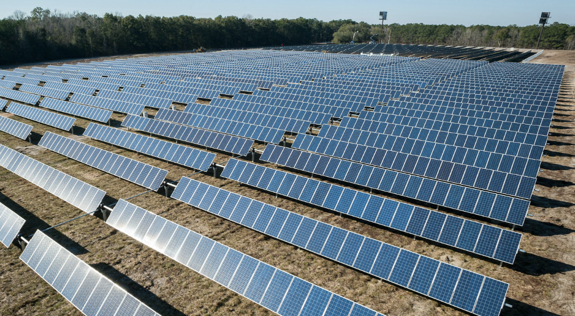
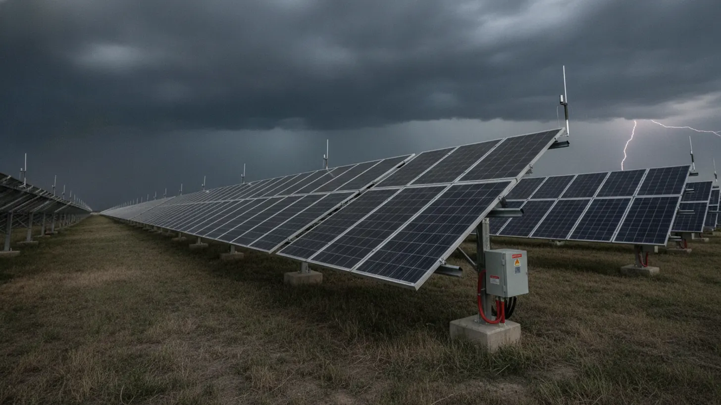
IEC 62305 splits any structure into Lightning Protection Zones (LPZ 0A, 0B, 1, 2, and higher) based on direct-strike exposure and induced surge intensity. On a utility-scale plant the tracker arrays sit in LPZ 0A (direct strikes possible, full lightning current), the enclosed inverter skids are LPZ 1 (partial current), and the SCADA cabinets inside the skid are LPZ 2. Every zone boundary needs bonded shielding and coordinated SPDs, which is the framework solar farm lightning protection IEC 62305 imposes on every downstream design decision.
The four Lightning Protection Levels (LPL I to IV) come from Annex A of IEC 62305-1 and set the interception efficiency between 84% and 99%. For utility-scale solar farms tied to bulk-power interconnection, LPL II or LPL I is typical because a single tracker outage costs revenue and a strike on the MV skid can propagate to the grid tie. The National Renewable Energy Laboratory risk framework recommends LPL analysis for any plant above 20 MW, and solar farm lightning protection IEC 62305 practice usually anchors on LPL II unless site-specific ground flash density pushes it higher.
We cover the details separately in Solar substation IEC 61850 GOOSE messaging: relay protection guide.
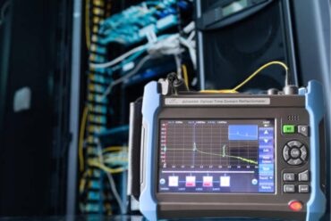
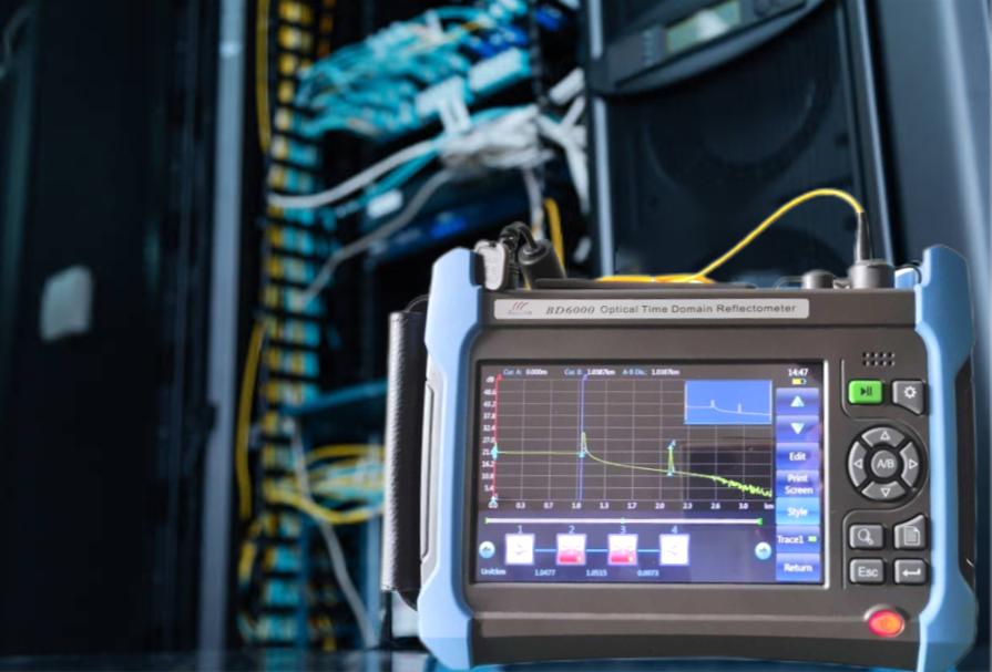
For a closer look at this, see Fiber optic installation solar farm: OTDR testing field guide.
We cover the details separately in Solar farm arc flash analysis NFPA 70E: IEEE 1584 and PPE guide.
We cover the details separately in BESS SCADA Integration for Utility-Scale Solar Plants: A Field Guide.
For a closer look at this, see Solar string IV curve tracing: field methods for degradation detection.
We cover the details separately in Solar drone thermal inspection: utility-scale hotspot field guide.
For a closer look at this, see IEEE 1588 PTP Time Sync for Solar SCADA: GPS Clock Field Guide.
For a closer look at this, see Solar Farm Revenue Metering: ANSI C12.20 Accuracy Field Guide.
We cover the details separately in DC Ground Fault Detection in Utility-Scale Solar: NEC 690.5 Field Guide.
We cover the details separately in Protection relay testing solar substation secondary injection guide.
For a closer look at this, see Solar substation transformer differential protection: IEEE C37.91 guide.
For a closer look at this, see Solar plant transformer DGA: dissolved gas analysis field guide.
External LPS design for solar tracker arrays under solar farm lightning protection IEC 62305
External protection uses three tools: air termination, down conductor, and earth termination. On a fixed-tilt or single-axis-tracker field, IEC 62305-3 permits any of three sizing methods: rolling sphere, protective angle, or mesh. Most utility-scale solar EPCs pick rolling sphere because tracker geometry changes with sun position and only the sphere method handles the moving envelope cleanly.
Air terminals mount on the highest tracker row and on inverter skid rooftops. Down conductors follow the tracker torque tube where feasible, with dedicated copper cable at every fifth row for redundancy. Bonding lugs and the earth ring conductor complete the external loop. The IEEE Std 998 and NFPA 780-2023 both cross-reference IEC methods, and NFPA 780 pins the 46 m rolling sphere radius for LPL I structures typical of a utility-scale solar farm collection substation. A solar farm lightning protection IEC 62305 design is only defensible if every tracker row is intercepted by a rolling sphere of the assigned LPL radius and every down conductor path is under 20 ohms end-to-end.
Mesh method for skid-mounted equipment
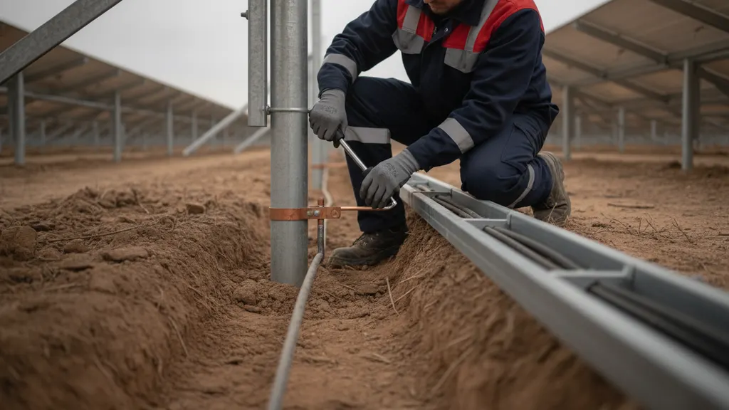
Mesh sizing works for the inverter skid, MV switchgear enclosure, and SCADA building. IEC 62305-3 Table 2 sets mesh width at 5 m for LPL I, 10 m for LPL II, 15 m for LPL III, and 20 m for LPL IV. Copper strap on 5 m grid across a 12 x 6 m skid roof gives LPL I coverage. The Department of Energy Solar Energy Technologies Office funded field research showing that uniform mesh sizing across shared skid designs cuts commissioning inspection failures.
We cover the details separately in Solar plant AC grounding and ground grid design: IEEE 80 field guide.
SPD selection at DC combiners and inverters under solar farm lightning protection IEC 62305
Internal protection uses SPDs at every zone boundary. IEC 61643-11:2011 defines Type 1 (Class I impulse test with 10/350 microsecond waveform), Type 2 (Class II with 8/20 microsecond nominal discharge), and Type 3 (fine protection at 8/20 microsecond, near-load only). On a utility-scale solar farm the SPD stack is normally Type 1 + Type 2 combined at the DC combiner box, Type 2 at the inverter DC input, Type 2 at the AC output, and Type 2 at the MV metering CT/PT enclosure. Solar farm lightning protection IEC 62305 coordination is the load-side residual voltage rule: for a 1500 V DC system, the continuous operating voltage U_cpv must equal or exceed module Voc_stc corrected to record-low site temperature (typically Voc_stc × 1.15 for a -10 °C cold-climate site), and the Type 2 protection level U_p must land at least 20 percent below the inverter DC bus lightning impulse withstand voltage to satisfy the energy coordination margin that IEC 62305-4 requires.
| Location | SPD Type | Impulse test | Rationale |
|---|---|---|---|
| DC combiner box | Type 1 + 2 | 10/350 us + 8/20 us | LPZ 0B to 1 boundary at array edge |
| Inverter DC input | Type 2 | 8/20 us | Fine protection for IGBT bus |
| Inverter AC output | Type 2 | 8/20 us | Coordinates with MV skid SPD |
| MV CT/PT enclosure | Type 2 | 8/20 us | Meter and revenue circuit protection |
| SCADA and control | Type 3 | Combination wave | Local point protection |
Selection also depends on the DC system voltage. A 1500 V DC bus needs SPDs rated for at least 1000 V DC continuous operating voltage (U_cpv), verified against the module Voc at record-low temperature. See our solar DC cable insulation testing guide for the withstand values that pair with SPD selection during commissioning.
Grounding and earth electrode integration
SPDs only work when the earth electrode network under them is at low impedance. IEC 62305-3 specifies Type A (individual rods or radials at each down conductor) or Type B (ring conductor around the structure) with a target earth resistance under 10 ohms measured at low frequency. On a utility-scale solar farm the ring conductor is bare copper sized per IEC 62305-3 Table 8, which sets the minimum bonding conductor cross-section at 16 mm² copper for paths not carrying partial lightning current and 25 mm² for paths that do; the ring itself typically runs at 50 mm² or larger to keep loop resistance below the 10-ohm target across the full array span, buried 0.5 to 1 m and bonded to every tracker table foundation, inverter skid, MV skid, and met station. The NIST transient network guidance is that all bonding paths within the LPZ 1 boundary should share a common reference plane to prevent side-flash voltages.
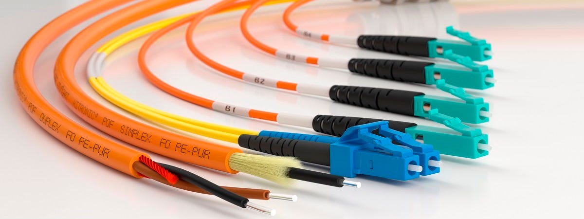
Equipotential bonding is the second half of the story. Every metal path that enters LPZ 1 (DC and AC power, SCADA fiber jackets, cathodic protection cables, water lines) must land on the main earthing bar with a bonding conductor sized per IEC 62305-3 Table 8. Fiber jackets are conductive on outdoor rated runs and get bonded exactly like power cable trays. Our fiber optic OTDR field guide covers the jacket bonding practice for outdoor plant. The solar farm lightning protection IEC 62305 rulebook treats grounding as the anchor for every SPD stack above it.
SPD inspection, testing, and O&M replacement cycle
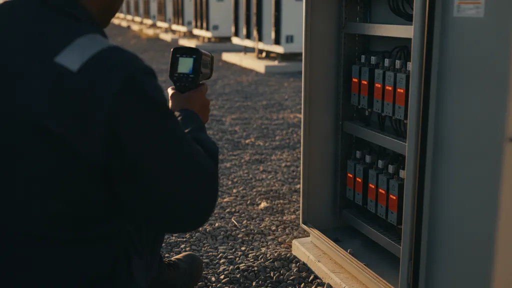
An SPD is a sacrificial device. Every strike or long-duration surge consumes MOV material and eventually the disconnect indicator trips or the varistor drifts out of spec. IEC 61643-11 defines the visual green/red indicator convention and the leakage-current test that verifies the module still holds its declared U_p. A solar farm lightning protection IEC 62305 O&M program runs an annual visual inspection, a thermographic scan under load, and a torque check on every bonding lug touched during commissioning per EPRI field procedures.
Replacement policy is straightforward: any SPD showing a red indicator, any SPD with a thermographic delta over 20 K above ambient enclosure temperature, and any SPD past 10 years since installation gets swapped even if the indicator still reads green. Post-strike walkdowns after a confirmed lightning event target the DC combiner boxes on the strike quadrant first. On a 120 MW single-axis tracker project in North Carolina, a storm cell that passed directly over the array resulted in three failed Type 2 SPDs across two combiner boxes, all located within four hours by working the mapped strike zone outward from the confirmed ground contact point. The OSHA lockout/tagout rules for MV disconnection apply to any SPD swap on energized circuits, and the SEIA O&M working group publishes template inspection checklists that plants can adapt. Our SCADA commissioning utility witness pack shows how to fold SPD test records into the plant handover documentation.
Frequently asked questions
Which standard defines solar farm lightning protection IEC 62305 compliance for US utility plants?
Utility-scale plants follow solar farm lightning protection IEC 62305 alongside NFPA 780-2023 with IEC 61643-11:2011 for surge protective device selection. NFPA 780 is the AHJ-adopted standard in most US jurisdictions and pins the LPL I rolling-sphere radius at 46 m (150 ft) for substation-scale structures. Interconnection utilities often add their own SPD coordination requirements at the point of common coupling, and some ISO/RTO tariffs explicitly reference IEC 62305 risk assessment as a deliverable within the interconnection study package. See the IEEE Std 998 for substation shielding methods that pair with the NFPA 780 rolling-sphere framework.
How do I pick between Type 1 and Type 2 SPDs at the DC combiner box?
Type 1 SPDs are for the LPZ 0B to 1 boundary where partial lightning current can enter the DC circuit, sized against the 10/350 microsecond impulse waveform per IEC 61643-11:2011. Type 2 SPDs handle induced surges only, sized against the 8/20 microsecond nominal discharge waveform. Utility-scale solar farms with tracker arrays outdoors and combiners at the array edge always need Type 1 or a combined Type 1+2 module. Type 2 alone is only defensible when the combiner is inside an LPZ 1 enclosure and separate Type 1 sits at the LPZ 0/1 boundary upstream.
What is the target earth electrode resistance for a solar farm LPS?
IEC 62305-3 sets the target under 10 ohms for the equipotential bonding system, measured at low frequency with a clamp-on or fall-of-potential method. High-resistivity soils (sandy or rocky sites) may require deep-driven rods, chemical ground enhancement, or extended ring conductors to hit that value. The NREL soil resistivity dataset is a starting point for design-stage assumptions but every plant needs a Wenner four-pin site survey with electrode spacings from 5 m to 30 m to profile resistivity variation across the site before final earthing design. Report the measured resistance on the commissioning witness pack.
How often should SPDs be inspected on a utility-scale solar plant?
Annual visual inspection of status indicators is the floor. Post-storm walkdowns after a confirmed strike within the plant footprint (or within 1 km based on Vaisala FALLS or Earth Networks lightning detection network data) are the operational trigger for a targeted DC combiner SPD check. Thermographic scans during peak generation catch varistors drifting toward end of life before the indicator trips. EPRI field practice recommends an annual thermographic sweep plus a five-year full leakage current test on every Type 2 module in DC combiners.
Does an SPD replace external lightning protection?
No. SPDs are internal protection for induced and partial-current surges only. Direct strikes to an unprotected tracker array will damage modules, tracker motors, and combiner-box components regardless of SPD condition. External lightning protection (air terminals, down conductors, earth ring) intercepts and drains the direct strike current before it can inject into the DC circuit. IEC 62305-4 explicitly requires coordinated external plus internal protection for any structure where lightning damage would exceed the tolerable risk defined in IEC 62305-2. A defensible solar farm lightning protection IEC 62305 program pairs external LPS with SPD coordination. Skipping the external LPS to save capex fails both IEC 62305 and NFPA 780 audit.
How does SPD selection interact with plant SCADA and controls?
SCADA cabinets, PLCs, and control power inside the inverter skid live in LPZ 2 and need Type 3 fine-protection SPDs on 24 VDC control busses, 120/240 VAC UPS feeds, and Ethernet/RS-485 data ports. Bond every SPD ground reference to the skid single-point earth bar to keep transient reference potential common. The ISA IEC 62443 hardening guidance also applies because a lightning-induced controller reboot is a security event as well as a reliability event. See our SCADA modernization roadmap for cabinet-level protection layout.