Solar DC cable insulation testing: HIPOT and megger commissioning guide
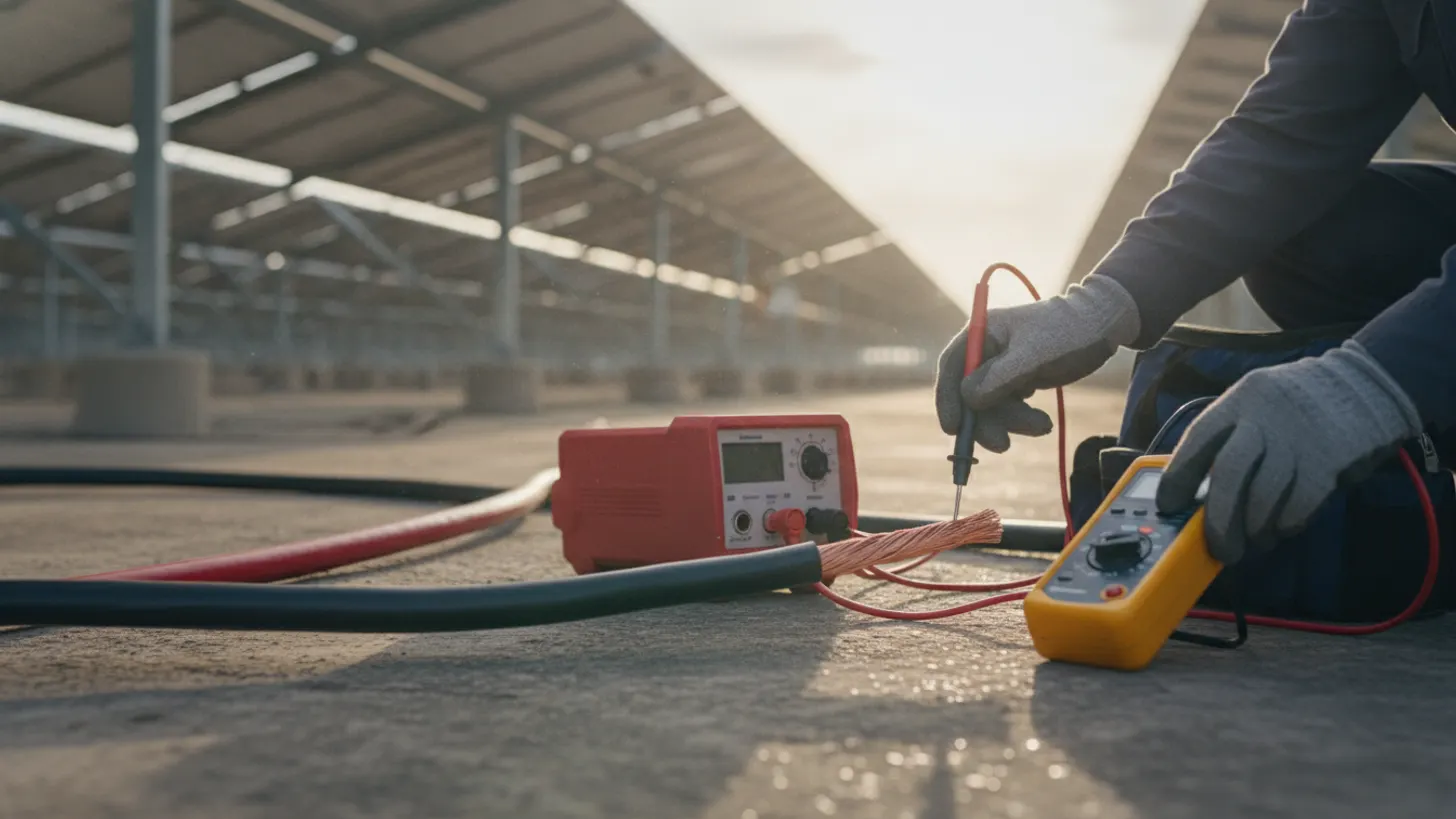
Solar DC cable insulation testing is the gate that stands between a mechanically complete PV plant and a revenue-earning asset accepted by the utility and the independent engineer. IEC 62446-1 sets a minimum insulation resistance of 1 megohm between every live conductor and protective earth, and utility witness packs will not close without those numbers. This guide walks commissioning teams through the standards, isolation steps, thresholds, environmental corrections, and record structures that hold up to independent review at plants above 20 megawatts.
IEC 62446-1 requirements for solar DC cable insulation testing
IEC 62446-1:2016 mandates 1 megohm minimum insulation resistance between every live conductor and protective earth before a PV string clears commissioning acceptance. Solar DC cable insulation testing is the measure within that six-test sequence most likely to delay energisation at utility-scale plants, because it is the result utility witness engineers check before the witness pack closes.
That 1 megohm floor applies to every string regardless of length or voltage class. Most healthy PV strings on new cable read in the hundreds or low thousands of megohms, so anything approaching the 1 megohm floor is a red flag rather than a pass. A good commissioning plan sets an internal alert threshold well above the standard minimum. The IEC standard also references IEC 60364-6 for the test voltage table, which pins the applied voltage to the system voltage class.
For a closer look at this, see Fiber optic installation solar farm: OTDR testing field guide.
For a closer look at this, see Solar SCADA commissioning: building the utility witness pack.
We cover the details separately in Protection relay testing solar substation secondary injection guide.
Safe isolation before solar DC cable insulation testing
No insulation test happens on a live PV array. OSHA 29 CFR 1910.333 requires that every DC circuit above 50 V be de-energised and placed under a written lockout/tagout procedure before test leads touch a conductor. For a 1,500 V DC plant, that is every circuit downstream of the module, and the isolation sequence has to be planned circuit by circuit rather than treated as a general array shutdown.
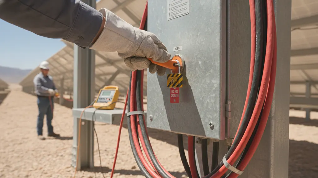
A defensible isolation sequence on solar DC cable insulation testing days follows a fixed order: open the inverter DC input, open the recombiner DC disconnect, open the combiner fused disconnects, verify zero volts at the combiner busbar with a rated meter, apply LOTO devices, and only then connect the insulation tester to the string under test. Cover unattended strings to prevent unexpected illumination effects. Route the isolation checklist into the same document set covered in our guide to solar SCADA commissioning witness packs, and align crew PPE with the shock and arc-flash boundaries defined in our NFPA 70E arc flash guide.
Pass/fail thresholds during solar DC cable insulation testing
Every project needs two thresholds documented before crews mobilise: the code-required pass value from IEC 62446-1, and an internal alert value set higher to catch marginal circuits. The code floor is 1 megohm. Solar DC cable insulation testing programs at a mature site treat anything below 40 megohms as an alert and anything below 10 megohms as an automatic re-test, because a healthy new PV string on dry cable will read hundreds of megohms.
The National Renewable Energy Laboratory has published PV plant reliability data showing that insulation degradation trends predict future ground-fault events better than any single measurement in isolation. Trending values across a fleet, rather than judging a single reading, is how a mature O&M program spots the string that will fail its second summer. The chart below shows how test voltage scales with system voltage class under IEC 60364-6.
| System voltage class | Test voltage (IEC 60364-6) | Minimum pass (IEC 62446-1) | Internal alert |
|---|---|---|---|
| Up to 500 V DC | 500 V DC | 1 megohm | Below 40 megohms |
| 500 V to 1,000 V DC | 1,000 V DC | 1 megohm | Below 40 megohms |
| 1,000 V to 1,500 V DC | 1,500 V DC (per plant spec) | 1 megohm | Below 40 megohms |
Environmental effects on solar DC cable insulation testing readings
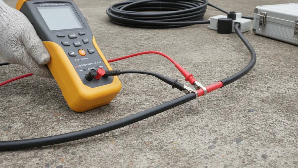
Insulation resistance halves for every 10 C rise in conductor temperature, per IEEE cable diagnostic practice, and dark PV DC feeders can reach 30 C above ambient in midday sun. A string reading 400 megohms at 20 C may therefore show only 100 megohms at 40 C with no defect present.
Humidity acts on connector faces and combiner terminations, not on the bulk cable insulation itself. Testing at 90% relative humidity after morning dew often produces borderline readings that clear once the array dries. A defensible commissioning procedure logs ambient temperature, relative humidity, and estimated conductor temperature at the moment of each measurement, and where practical normalises readings to a reference temperature of 20 C before comparing against pass/fail thresholds. Longer strings and larger combiner circuits have more surface area and therefore a lower absolute reading for the same insulation condition; that geometry effect is why per-string tests, not whole-array tests, remain the acceptance measurement of choice. Anchor these environmental logs to the same weather record described in our DAS irradiance and weather QA guide.
Documentation standards for solar DC cable insulation testing records
Per IEC 62446-1, every solar DC cable insulation testing circuit record must include the string identifier, applied test voltage, measured insulation resistance, ambient temperature, relative humidity, tester model, tester serial number, calibration certificate reference, calibration expiry date, tester operator name, and time of the reading. Missing any single one of those fields is the most common reason acceptance packages are returned during independent engineer review.
In REIG Solar’s commissioning practice across more than 20 utility-scale PV plants in the Southeast and Mountain West, we have had an acceptance package returned because a tester’s calibration certificate had expired two days before the site mobilisation date. That gap delayed commercial operation approval by three weeks. Every field in the IEC 62446-1 record set has a reason, and calibration certificate expiry is the one most commissioning teams learn about the hard way.
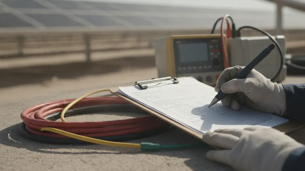
Structure the deliverable as one continuous record per string across the plant lifecycle. That means initial commissioning solar DC cable insulation testing lands in the same record schema as year-two O&M retests, so trending is possible without a data migration. The US Department of Energy Solar Energy Technologies Office published lifecycle reliability guidance that specifically calls out longitudinal insulation trending as a leading indicator of ground-fault risk. Complement the electrical records with our NEC 690.5 DC ground fault detection field guide so the fault-side monitoring architecture is documented alongside the acceptance measurements.
For a closer look at this, see Solar DAS commissioning: irradiance and weather QA standards.
Frequently asked questions
What is the minimum insulation resistance required by IEC 62446-1 for a PV string?
IEC 62446-1:2016 sets a minimum insulation resistance of 1 megohm between every live conductor and protective earth for every PV string tested during commissioning. That value is a floor, not a target: a new PV string on dry cable typically reads in the hundreds or low thousands of megohms, so anything near the 1 megohm floor should be flagged for investigation before the string is accepted. A commissioning program that only records pass/fail against the 1 megohm floor loses the trending value that catches early cable degradation years before it becomes a ground fault.
What test voltage should I apply for a 1,500 V DC PV system?
IEC 60364-6 sets 500 V DC test voltage for systems up to 500 V DC and 1,000 V DC test voltage for systems rated 500 V to 1,000 V DC. Above 1,000 V DC, project specifications and manufacturer datasheets typically call for a 1,500 V DC test voltage matched to the system class, and most plant technical specifications on utility-scale sites echo that value. Always confirm the exact number against the specific inverter and cable manufacturer datasheets before the crew mobilises, because some inverter DC input stages have lower withstand ratings than the cable itself.
Do I need to disconnect combiners before insulation testing?
Yes. OSHA 29 CFR 1910.333 requires every DC circuit above 50 V to be de-energised under written lockout/tagout before an insulation tester connects to the circuit. On solar DC cable insulation testing days that means opening the inverter DC input, opening recombiner disconnects, opening combiner fused disconnects, verifying zero volts at the combiner busbar with a rated meter, and applying LOTO devices before the tester is connected to any string. Skipping any step in that sequence risks personnel injury and inverter damage.
How does temperature affect insulation test results in the field?
Insulation resistance falls roughly by half for every 10 C rise in conductor temperature, and cable insulation on dark PV DC feeders can run 30 C or more above ambient in midday sun. A string that would read 400 megohms at 20 C may read only 100 megohms at 40 C without any real degradation. Log ambient and estimated conductor temperature at every reading, and where a project permits normalise readings to 20 C before applying pass/fail thresholds. The temperature correction guidance in IEEE cable diagnostic practice is the reference most commissioning teams use.
What documentation do utilities require for insulation test records?
Utility witness packs typically require, per IEC 62446-1, the string identifier, applied test voltage, measured insulation resistance, ambient temperature, relative humidity, tester model, tester serial number, calibration certificate reference and expiry date, tester operator name, and time of the reading. Independent engineers reviewing project acceptance often demand the same record set plus a signed statement confirming the test was performed under a written procedure. Assemble the records in the same schema you plan to use for lifecycle O&M so year-two retests compare directly against commissioning baselines.
Can I use a standard megger or do I need a hipot tester for solar strings?
For the routine solar DC cable insulation testing required by IEC 62446-1, a standard insulation resistance tester with a 1,000 V DC or 1,500 V DC output range and a suitably wide megohm range is sufficient for acceptance. Full high-potential DC withstand testing at multiples of rated voltage is not required by IEC 62446-1 for routine string acceptance and can damage inverter DC input circuitry if applied without isolation. Reserve DC HIPOT testing for factory acceptance, forensic investigation, or specific project specifications that call it out explicitly.