
Solar farm fiber optic testing: OTDR, splice QA, commissioning
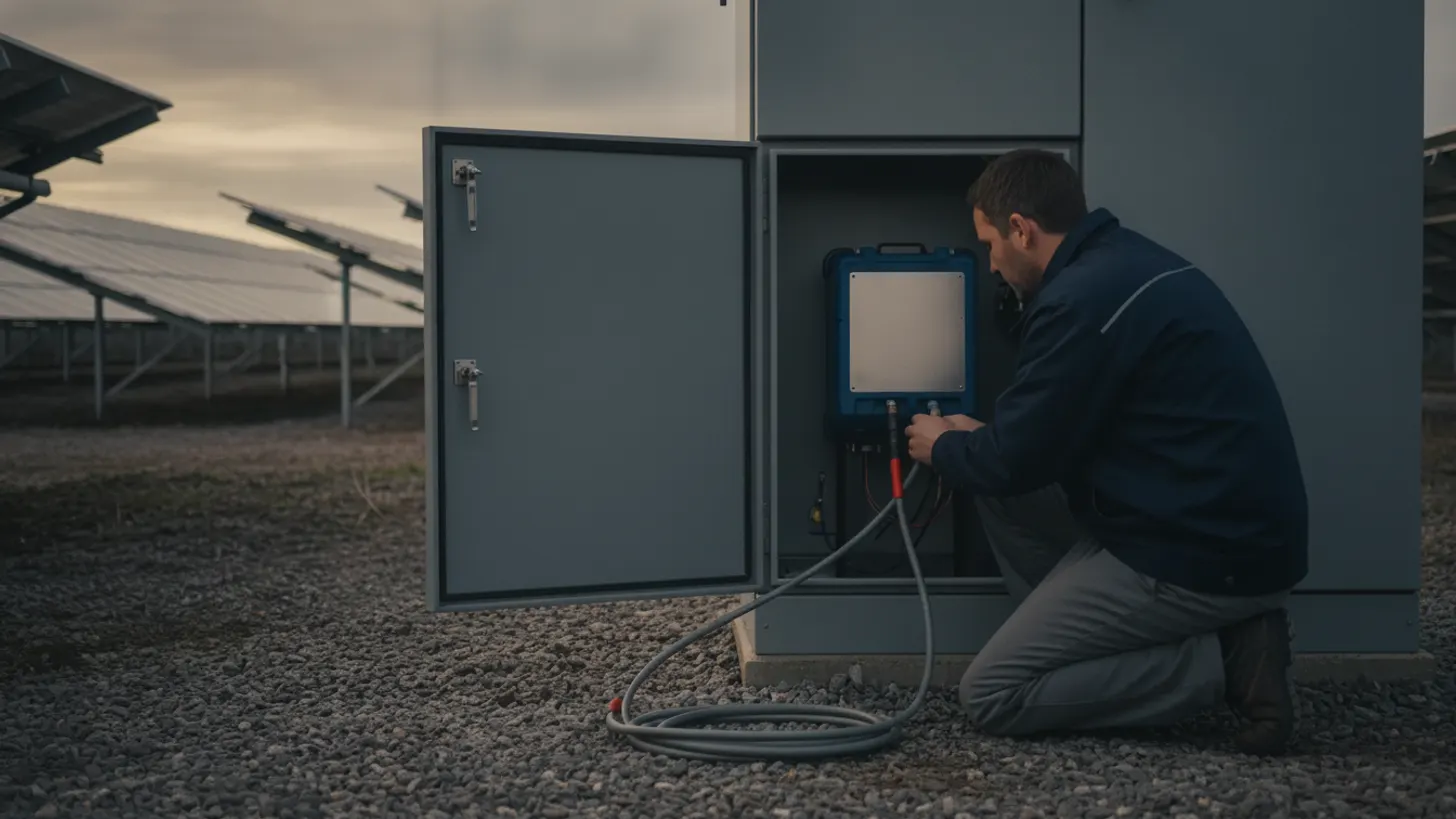
Fusion splices on a utility-scale plant backbone are usually held to 0.3 dB each and a mated connector pair to 0.75 dB, the loss limits most EPC specifications inherit from TIA-568 cabling practice. Miss them and the link still shows a light on day one, then starts dropping polls when the enclosure hits 45 C in August. Solar farm fiber optic testing exists to find that lost margin before handover, not after it.
What solar farm fiber optic testing must finish before SCADA commissioning
Before an integrator energizes a single data concentrator, the fiber plant needs four finished records: end-face inspection on every connector, insertion loss measured with a light source and power meter, bidirectional OTDR traces on every span, and an as-built label schedule. Solar farm fiber optic testing that stops at a link light proves almost nothing.
The fiber plant on a utility-scale site is not one network. It is normally a single-mode backbone from the substation control building out to each inverter block, plus short multimode or copper drops inside the skid. Every boundary adds a mated pair, and every mated pair adds insertion loss, reflectance, and a contamination risk. NREL best practices guidance for photovoltaic operations and maintenance treats monitoring and communications availability as part of plant performance management rather than an IT afterthought, and US Department of Energy Solar Energy Technologies Office program material frames the same point: a dark pair means a blind block.
Sequence matters more than instrument choice. Test and record before the trenches close, and coordinate with the crews running medium voltage cable testing on the collection system so duct bank work does not bury an unverified splice. A closure that passes on the reel and fails after backfill is the most expensive defect class on the job, because the repair is an excavator. REIG learned this directly on a 140 MW project in Pecos County, Texas, during combiner skid trenching in March 2024. The pre-burial trace read clean, but a grading crew working the next row nicked a duct, and only the post-backfill retest caught 0.6 dB of new loss at a hand hole three spans away. Skipping that second trace to save a day on the schedule would have handed the owner a plant with one blind combiner skid at energization. Capture the pre-burial trace, repeat after backfill, and compare the two.
How solar farm fiber optic testing uses OTDR to identify splice, connector, and route defects
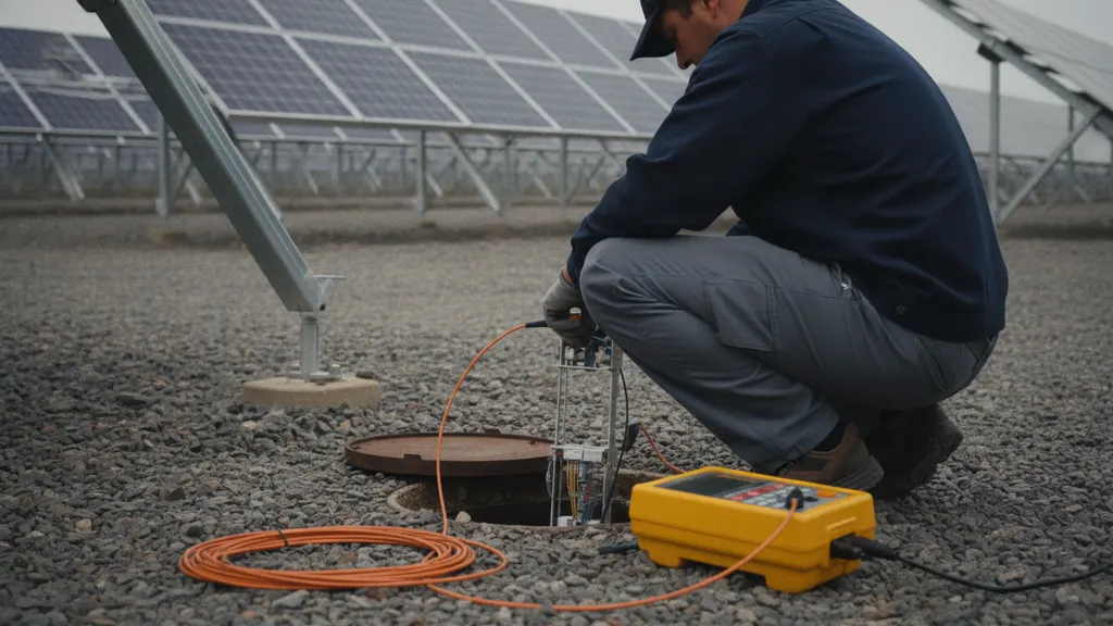
An OTDR launches a pulse down the fiber and measures backscattered and reflected light against elapsed time, so it reports where loss happens rather than only how much. A power meter says the link is 2.1 dB down. An OTDR says 0.9 dB of that sits at a splice 1,840 m out, next to a hand hole.
Read events by signature. A fusion splice shows a step down with little reflectance. A mated connector shows a reflective spike with a step. A macrobend shows loss that grows at 1550 nm while staying modest at 1310 nm, which is why both wavelengths are tested. A clean break drops the trace to the noise floor. Crush damage from a roller or a staple shows a non-reflective step where the as-built lists no splice at all.
Technique decides whether the readings are trustworthy. Use launch and receive cables so the first and last connectors are measurable instead of hidden in the dead zone. Average in both directions. Keep the pulse width short enough to resolve closely spaced events, then widen it for long spans. Instrument calibration follows IEC 61746-1, the IEC calibration standard for optical time-domain reflectometers, and solar farm fiber optic testing records should name the instrument, its serial number, and its calibration date.
The attenuation coefficient a span budget is built against depends on fiber type and wavelength.
Which splice-loss and optical-power results solar farm fiber optic testing should record
Acceptance records need absolute numbers against stated limits, never a pass stamp alone. Most EPC specifications hold a fusion splice to 0.3 dB, a mechanical splice to 0.3 dB, and a mated connector pair to 0.75 dB, following TIA-568 cabling practice, then compare measured end-to-end loss against a budget calculated for that specific span.
Build the budget before the test, not after. A 3 km single-mode span at the 0.4 dB/km limit for 1310 nm carries 1.2 dB of fiber loss; add four fusion splices at 0.3 dB and two connector pairs at 0.75 dB and the calculated worst case is 3.9 dB. The IEEE 802.3 Ethernet standards family allows 4.5 dB of channel insertion loss for 1000BASE-LX, so that span passes with very little room left. Solar farm fiber optic testing that skips the budget calculation cannot tell a marginal link from a healthy one.
Record the OTDR event table and the insertion loss measured with a light source and power meter at both wavelengths. The two often disagree, and the disagreement is informative: OTDR event loss is computed from backscatter and can under-report a dirty connector, while the power meter reports what the transceiver actually receives.
| Test | What it proves | Typical limit | Standard reference |
|---|---|---|---|
| End-face inspection | Connector cleanliness and physical damage | Zone-based scratch and defect criteria | IEC 61300-3-35 |
| Bidirectional OTDR | Event location, splice and connector loss, route length | 0.3 dB per fusion splice | IEC 61746-1 (instrument calibration) |
| Insertion loss | End-to-end loss the transceiver sees | Within calculated span budget | TIA-568 and IEEE 802.3 link budget |
| Optical return loss | Reflectance at each mated pair | Per project specification | IEC connector test methods |
How to inspect, clean, label, and document fiber links
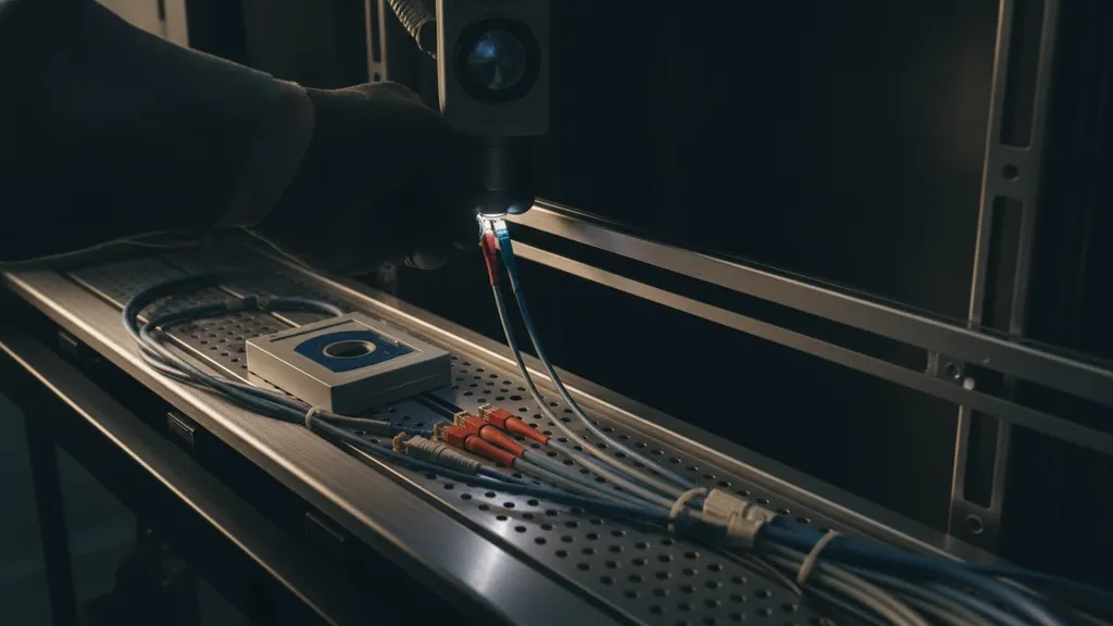
Contamination delays more commissioning calls than bad splices do. Inspect every end face with a video microscope before every mate and grade it against the zone criteria in IEC 61300-3-35, the IEC visual inspection method for fiber connector end faces. A dust cap is not a clean cap. Solar farm fiber optic testing starts at the end face.
Work the clean-inspect-clean loop: inspect, clean dry, inspect again, and move to a wet-to-dry clean only when the dry pass fails. Clean bulkhead adapters as well as patch cords, because mating a clean jumper into a dirty adapter transfers the debris and can pit both faces under power. Follow OSHA guidance on laser and optical radiation hazards and never inspect a fiber that might be live.
Labeling is part of the test, not paperwork afterward. Label both ends of every pair with tray, port, and fiber identity matching the as-built drawing, because the integrator mapping tags for OPC UA SCADA integration and the engineer provisioning IEEE 1588 time synchronization both depend on knowing which physical path serves which block. EPRI research on PV plant monitoring and data acquisition points at data quality as a recurring source of performance uncertainty, and ambiguous fiber labeling is one of its quieter causes.
What an EPC solar farm fiber optic testing package should contain for COD acceptance
An acceptance package is a defensible record set: native OTDR trace files for every span in both directions, insertion loss results at both wavelengths, end-face images for every connector, splice closure records with tray maps, the as-built label schedule, and instrument calibration certificates.
Insist on native trace files rather than PDF screenshots. A trace file can be re-analyzed years later with different event thresholds when a link starts degrading; a flattened image cannot. Include instrument model, serial number, calibration date, pulse width, index of refraction, and operator name. Calibration traceability chains back to national standards, and NIST optical fiber metrology programs maintain the references those chains terminate at. Solar farm fiber optic testing done with untraceable instruments is an opinion, not a record.
Solar farm fiber optic testing deliverables the owner should keep
Keep the fiber package with the cyber baseline. The port inventory built during labeling feeds the asset list used for SCADA cybersecurity controls, and spans carrying protection traffic such as IEC 61850 GOOSE messaging deserve their own marked records and loss margins. Owners taking over a registered plant should also read the package against telemetry and data obligations in the NERC reliability standards library, because the fiber plant is what makes those obligations physically possible.
Frequently asked questions
Do I need an OTDR if the fiber link already passes a power meter test?
Yes. A power meter reports total end-to-end loss and nothing about where that loss sits, so a link can pass while a single contaminated connector consumes most of the margin. Solar farm fiber optic testing uses the OTDR to locate and quantify each event, which gives the O&M team a baseline trace to compare against years later when a span starts erroring. Instrument accuracy for that comparison depends on calibration under IEC 61746-1 for optical time-domain reflectometers. Run both tests: the meter proves the link works today, the trace explains why.
What splice loss is acceptable on a utility-scale solar fiber run?
Most EPC specifications accept 0.3 dB for a fusion splice and 0.75 dB for a mated connector pair, limits drawn from TIA-568 cabling practice, but the number that matters is the span budget. Add fiber attenuation at the standard coefficient, every splice, and every connector pair, then compare the total against the transceiver allowance. The IEEE 802.3 Ethernet standards family permits 4.5 dB of channel insertion loss for 1000BASE-LX. A 0.4 dB splice on a short span may be fine; a 0.25 dB splice on a long one may not be.
Why do my OTDR readings change when I test from the other end?
Because backscatter coefficients differ slightly between two spliced fibers. When mode field diameters do not match, the splice reads high from one direction and can read as a gain from the other, an artifact technicians call a gainer. The fix is bidirectional testing: measure from both ends and average the two event losses for the true value. Fiber geometry tolerances that produce the mismatch are specified in ITU-T G.652, and inspection of the mated faces follows IEC 61300-3-35 end-face criteria. Any acceptance record showing one-direction traces only is incomplete.
How often does an OTDR need calibration?
Follow the manufacturer interval, which is commonly annual, and keep the certificate with the test package. Calibration covers distance accuracy, loss linearity, and active range, and it is what lets two different crews on two different days produce comparable traces on the same span. The reference artifacts that calibration laboratories chain to are maintained by programs such as NIST optical fiber metrology. In practice the calibration date is the first thing a careful owner checks on a submitted report, because an out-of-calibration instrument invalidates every trace in the binder.
Who is responsible for fiber testing, the EPC or the SCADA integrator?
The EPC normally owns the physical layer: installation, splicing, inspection, loss testing, and the as-built label schedule. The integrator owns everything above it, including switch configuration, protocol mapping, and historian points. Problems appear at that seam, so the contract should name the standards, the limits, and the record format before mobilization. NREL photovoltaic operations and maintenance guidance treats monitoring reliability as part of plant performance, which argues for a single named owner of link quality through commissioning rather than a handoff with no measured baseline.
What should an owner ask for before accepting the fiber plant at COD?
Ask for native bidirectional trace files per span, insertion loss at both wavelengths with the calculated budget shown beside each measurement, end-face images for every connector, splice closure and tray records, an as-built label schedule matching field tags, and calibration certificates for each instrument. Then spot-check a few spans yourself. Solar farm fiber optic testing records are only useful when they are reproducible, and public program material from the US Department of Energy Solar Energy Technologies Office supports treating plant data systems as long-lived assets worth documenting to that level.