
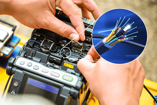
Fiber Optic Splicing & OTDR Testing
Dirty splices kill communication rings. We field certified fusion splicing crews and provide the OTDR trace reports required for utility handover.
You can't troubleshoot a network if the glass is broken.
Most SCADA integrators sit behind a desk and wait for the EPC to finish the network. When pings drop, they blame the fiber. The EPC blames the switch. Your COD slips. We close that loop — splice it, test it, and hand you the trace.
OTDR · 1310nm · OS2
Trunk fiber span — sample trace
10.00 km · 2.46 dB total
IEC 61280-4-2
Bi-dir
1310 + 1550 nm
Splice loss
≤ 0.10 dB
fusion · per joint
Connector
≤ 0.50 dB
UPC · per pair
- Single-mode & multi-mode fusion splicing
- Bi-directional OTDR @ 1310 + 1550 nm
- Redundant ring topologies (RSTP)
Defensible acceptance — every strand, every splice.
OTDR Trace Reports
PDF traces for every strand at 1310 nm and 1550 nm — bi-directional, in line with IEC 61280-4-2. Splice loss documented per joint, connector loss documented per pair.
Splice Diagrams
Color-coded as-built diagrams for every splice tray, ring vault, and patch panel. Hand-over package includes physical labels matching the diagram.
Remediation
When the trace finds macro-bends, contaminated ferrules, or bad pulls, we re-splice and re-test on the same trip. The package leaving site is one we will sign.
Estimate your link power budget.
Quick check before procurement — calculate total dB loss for your ring length and splice count.
Fiber Loss Budget Calculator
Estimate maximum allowable dB loss for single-mode utility networks.
*Estimates based on TIA/EIA-568-B.3 standards. REIG utilizes advanced OTDR testing to verify actual insertion loss is significantly lower than calculated maximums.
Frequently Asked Questions
Ensure your fiber ring is flawless.
Clean splices, zero finger-pointing.