
Medium voltage cable testing solar farm VLF: tan delta field guide
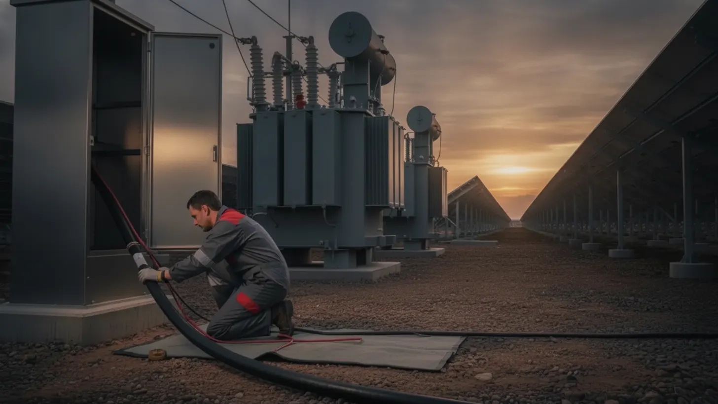
IEEE 400.2-2013 sets 0.1 Hz very low frequency (VLF) withstand at 3Uo, roughly 60 kV rms on a 34.5 kV collector circuit, because DC hipot injects space charge into aged XLPE and can seed the very fault it was meant to find. That single number is why medium voltage cable testing solar farm VLF programs now dominate acceptance work on utility-scale PV, and why tan delta, the ratio of resistive to capacitive leakage current in the insulation, travels with the cable as trend data for its whole service life.
Fault modes that make medium voltage cable testing solar farm VLF necessary
Solar collector cable fails from moisture ingress, thermal cycling, and splice workmanship, not from sudden overvoltage. Those mechanisms degrade slowly and stay invisible to an insulation resistance megger. Very low frequency diagnostics expose them while the plant is still in commissioning, which is the whole reason medium voltage cable testing solar farm VLF procedures exist.
Water treeing in direct-buried collector runs
A 34.5 kV collector circuit spends its service life direct buried in a trench that floods after heavy rain. Moisture migrates into the XLPE wall, and under sustained AC stress it grows branching water trees that thin the effective insulation. The added dielectric loss appears in a tan delta measurement long before the cable punctures. EPRI report TR-108400 on XLPE distribution cable condition assessment sets the diagnostic bands the field still works from, placing mean tan delta above 4x10⁻³ in the heavily degraded range.
Electrical trees, voids, and splice workmanship
Electrical trees start at a contaminant, a void, or a protrusion in the semiconducting screen, and they emit partial discharge as they propagate. Workmanship is the other large defect population on a new build: stress cones seated off center, semicon layers cut too deep, grit trapped under heat shrink. None of that fails an insulation resistance check. All of it shows in diagnostics, which is why medium voltage cable testing solar farm VLF work belongs in the acceptance scope rather than a later warranty claim. Our DC cable insulation testing and megger commissioning guide covers the low voltage side of the same plant.
Setting up medium voltage cable testing solar farm VLF tan delta on a 34.5 kV feeder
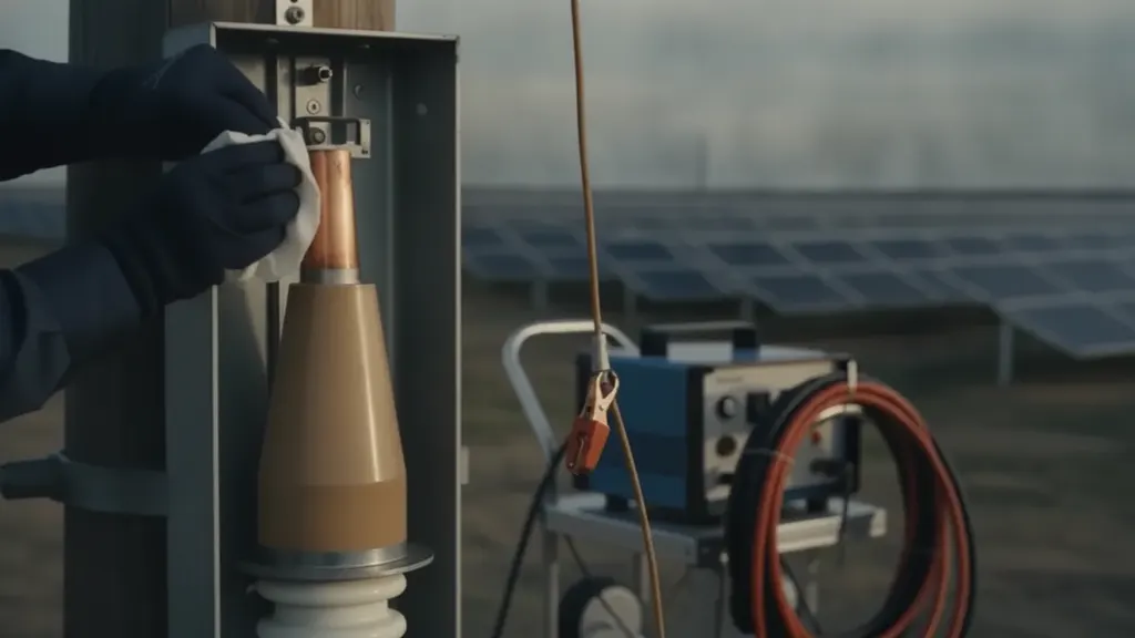
A 34.5 kV collector feeder reaches 3Uo, about 60 kV rms, the moment the VLF set is at full output, so clean, dry terminations and complete isolation must be ready first. Open both ends, ground and discharge, lift surge arresters and potential transformers. Medium voltage cable testing solar farm VLF setup succeeds or fails on that preparation.
The working frequency is 0.1 Hz, and the acceptance withstand level for a 35 kV class circuit is 3Uo, close to 60 kV rms. Take tan delta readings at 0.5Uo, 1.0Uo, and 1.5Uo, with repeat measurements at each step, before the withstand run. Three numbers come out of that sequence: mean tan delta at Uo, differential tan delta between the 1.5Uo and 0.5Uo steps, and tan delta stability, the spread across repeat readings at one step. The IEEE 400.2-2013 guide to field testing shielded power cable systems using very low frequency tabulates all three.
Size the VLF source to the capacitive load. A long collector feeder and its splices present real capacitance, and an undersized set will not reach 3Uo at 0.1 Hz. Log conductor temperature, ambient temperature, and humidity with every reading, because tan delta moves with temperature and a trend built from unrecorded conditions cannot be compared year over year. Calibration on the bridge and divider should trace to NIST measurement and calibration services. On a live site, medium voltage cable testing solar farm VLF planning is also a switching problem tied to the plant operating procedure.
Tan delta and partial discharge thresholds in medium voltage cable testing solar farm VLF work
A collector feeder REIG tested at a 200 MW project in West Texas read a mean tan delta of 5.8x10⁻³, inside the further study band, but its differential tan delta stayed flat across all three voltage steps. That pattern argued for uniform aging rather than a local defect, so the feeder went back into service with a shortened retest interval instead of an unnecessary splice. No single number condemns a cable. Medium voltage cable testing solar farm VLF assessment reads three tan delta figures together, then weighs partial discharge inception voltage and magnitude against them. A feeder that holds 3Uo for the full withstand period can still be flagged when its loss numbers sit in the further study band.
For polyethylene insulated cable, mean tan delta at Uo below 4x10⁻³ calls for no action, the range from roughly 4 to 80 calls for further study, and anything higher calls for action. Differential tan delta, the tip-up across the voltage steps, separates uniform aging from voltage dependent defects. Stability, the spread of repeat readings, catches intermittent conduction that a single reading averages away.
Partial discharge adds location. An offline PD measurement at VLF gives inception and extinction voltage referenced to Uo, apparent charge in picocoulombs, and a time-domain position along the run that usually lands on a splice or a termination. Inception below Uo means the defect is discharging in normal service. For extruded cable rated above 30 kV, acceptance voltage and duration are specified in IEC 60840:2020 for extruded insulation power cables, and IEEE standards for field PD measurement on shielded cable systems cover the sensitivity and calibration work that makes a pC number meaningful.
| Method | What it detects | Field criterion | Reference |
|---|---|---|---|
| VLF withstand at 0.1 Hz | Gross defects that would fail under service stress | Holds 3Uo for 30 to 60 minutes without breakdown | IEEE 400.2-2013 |
| VLF tan delta | Bulk aging, water trees, absorbed moisture | Mean, differential, and stability read together | IEEE 400.2-2013, EPRI TR-108400 |
| Offline partial discharge | Localized voids, splice and termination defects | Inception above Uo, magnitude trended | IEEE field PD guidance |
| DC hipot | Little on extruded cable, adds space charge | Not applied to service-aged XLPE | IEEE 400.2-2013 |
| Insulation resistance | Gross moisture and connection errors | Screening step, not a diagnostic | IEEE 400 series |
Write the reject rule into the test plan before the crew mobilizes. Deciding on the tailboard what counts as a failure turns medium voltage cable testing solar farm VLF results into a negotiation with the EPC instead of an acceptance gate.
Isolation and grounding before medium voltage cable testing solar farm VLF work begins
Nothing about this test is routine on a live plant. The circuit gets switched out, locked out, proven dead, and grounded at both ends before a lead lands. Adjacent feeders stay energized, the inverters stay hot on the DC side, and the 34.5 kV bus keeps carrying export power.
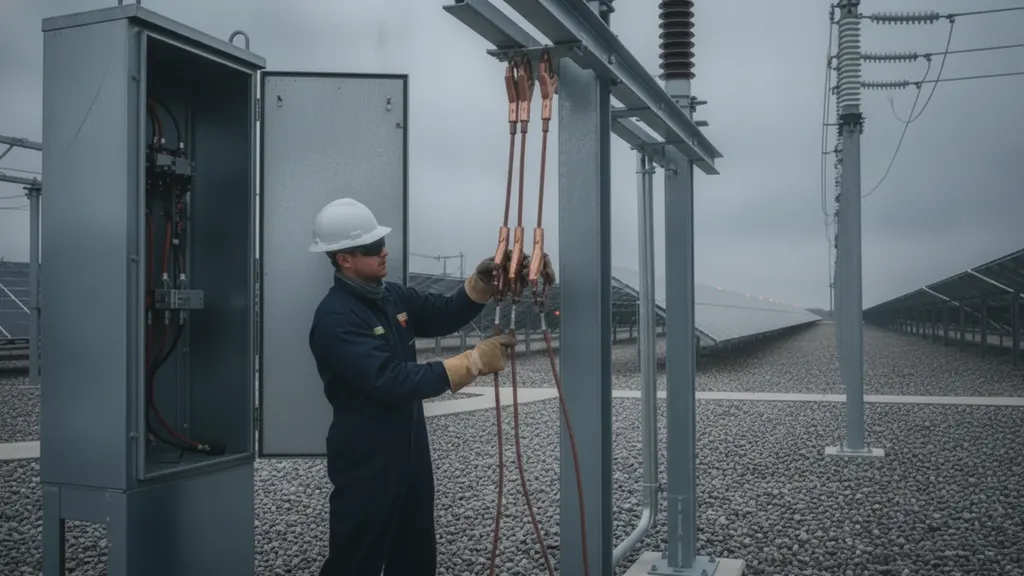
Build the switching order around a written clearance: open the feeder breaker, rack out or open the disconnect, apply lockout, test for absence of voltage with a rated instrument, then apply cluster grounds at both ends. Lift surge arresters and potential transformers before the far end is released for testing. Those steps sit inside the electrical safe work practices of OSHA 29 CFR 1910.269 for electric power generation, transmission, and distribution, and the shock and arc flash boundaries come from your incident energy study. Our solar farm arc flash analysis and PPE guide covers the labeling side. Medium voltage cable testing solar farm VLF work also needs a radio protocol with the control room, because the SCADA operator has to know a circuit is under test before anyone tries to close on it. NERC reliability expectations for registered generators cover the same coordination.
The far end becomes an energized point the moment the set fires, so post a guard, rope the exclusion zone, and keep an observer on site radio. After each voltage step, discharge through the set and leave temporary grounds applied for several times the test duration, since a long cable holds recoverable charge well after the source drops. Temporary ground cable has to be sized for the available fault duty of the grid it connects to, which ties back to the IEEE 80 ground grid design field guide.
Test records and trend data from medium voltage cable testing solar farm VLF programs
A medium voltage cable testing solar farm VLF record needs more than a dozen data fields to survive five years of comparison, since a bare pass or fail number strips out the weather, crew, and instrument context a trend needs. An engineer five years out has to match the same circuit run to run and see whether the loss curve moved.
Each record should name the circuit and its cable schedule reference, conductor size and insulation type, circuit length and splice count, conductor and ambient temperature, relative humidity, instrument model and serial number with calibration date, applied voltages, all tan delta readings at each step, PD inception and magnitude where measured, withstand duration, and the technician and witness who signed. That package belongs in the turnover binder alongside the rest of the acceptance evidence, which our solar SCADA commissioning witness pack guide lays out.
Then move the data somewhere it can be trended. A CMMS record keyed to the same circuit tag the SCADA system uses lets a repeat test drop straight onto the prior curve, and it lets cable health sit beside availability and MTTR in the plant O&M KPI benchmarking review. Condition-based intervals for medium voltage cable testing solar farm VLF work are supported by NREL research on PV plant reliability and operations, and the US Department of Energy Solar Energy Technologies Office publishes related work on utility-scale plant performance.
Frequently asked questions
Why can we not DC hipot a solar collector cable the way we used to?
DC hipot injects space charge into service-aged extruded insulation. The trapped charge distorts the field inside the XLPE wall, and when the circuit returns to AC service that distortion can start the failure the test was meant to prevent. Field practice moved to 0.1 Hz very low frequency AC because it stresses insulation in a way that resembles service conditions while keeping the test set small enough to carry to a trench. The IEEE 400.2-2013 field testing guide documents the procedure and its acceptance levels.
How long does a VLF withstand test take on one collector feeder?
Plan on 30 to 60 minutes of applied voltage per circuit at 3Uo, and expect setup, grounding, and discharge to take longer than the energized portion. Tan delta stepping adds time, since each voltage step needs repeat readings before the withstand run starts. A prepared crew that has already isolated the feeder and lifted its arresters can often work through several circuits in one shift. Acceptance voltage and duration for extruded cable rated above 30 kV are set out in IEC 60840:2020.
What tan delta value means the cable should be replaced?
No single reading condemns a cable, but the bands are well established. EPRI report TR-108400 on XLPE condition assessment places mean tan delta above 4x10⁻³ in the heavily degraded range for polyethylene insulation, with readings between roughly 4 and 80 calling for further study and higher numbers calling for action. Read that alongside differential tan delta across the voltage steps and the stability of repeat readings at one step. A high mean with a flat tip-up points at uniform aging rather than a local defect.
Can the inverters and transformers stay connected during the test?
No. The feeder has to be an isolated length of cable with both ends open. Surge arresters, potential transformers, and any connected switchgear or pad-mount transformer will clamp the test voltage or draw current that corrupts the loss measurement, and several of those components can be damaged at 3Uo. Inverters stay locked out on both the AC and DC sides. That isolation work, along with lockout and grounding, falls under the electrical safe work rules in OSHA 1910.269 for power generation and distribution.
Does VLF testing damage healthy cable?
Applied correctly, no. The 0.1 Hz waveform develops peak stress comparable to service voltage over a longer cycle, so sound insulation sees nothing it does not already see every day. What the test does is find defects that were going to fail anyway, on a scheduled morning with a crew on site rather than at 2 a.m. in July. Staying inside the voltage and duration limits in the IEEE 400.2-2013 guide is what keeps the test diagnostic rather than destructive.
How often should an operating solar plant retest its collector cables?
Most operators baseline at commissioning, retest after any splice repair or dig-in, and then run a diagnostic sweep on a multi-year cycle set by circuit age and trench conditions. Wet trenches and older cable shorten the interval. Tie the schedule to the asset management plan rather than the calendar, and feed each result into the same record set, so medium voltage cable testing solar farm VLF results build a curve instead of a folder of one-off numbers. NREL research on PV plant reliability and O&M practice supports condition-based intervals.