
Solar power plant controller commissioning: setpoints and telemetry
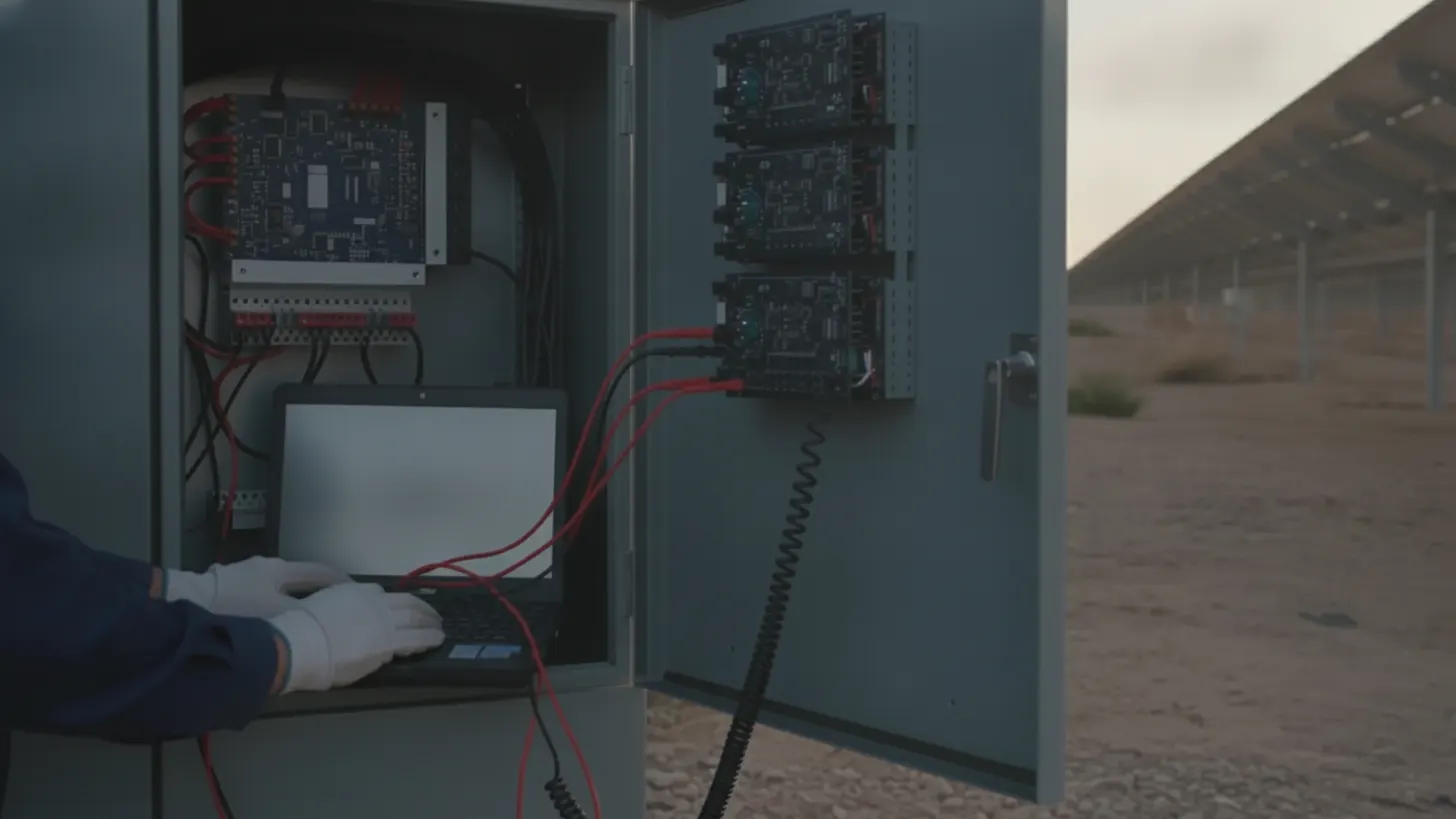
NERC PRC-028-1 became effective April 1, 2025, and it treats disturbance monitoring and reporting for inverter-based resources as a reliability obligation rather than a reporting courtesy. That raises the bar for solar power plant controller commissioning: the test team has to prove that every setpoint lands correctly at the point of interconnection, and that every command, acknowledgment, and timestamp survives the trip to the utility control center.
What solar power plant controller commissioning must test
Solar power plant controller commissioning proves every function the controller performs on behalf of the grid operator: setpoint tracking, ramp limiting, curtailment, voltage and reactive regulation, frequency droop, and fallback behavior when the utility link drops. Each function needs a written pass criterion before the first command is issued.
The plant controller sits between the utility control center and the inverter fleet, so its test scope spans four layers that fail in different ways:
- Regulation functions. Active power limit and ramp rate, reactive power mode, closed-loop voltage regulation with droop and deadband, power factor mode, and frequency droop response. Plants with fast frequency obligations should time that response path as described in our guide to solar plant frequency response and synthetic inertia.
- Supervisory functions. Dispatch allocation across inverter blocks, headroom and availability tracking, curtailment accounting, and interaction with trackers or co-located storage.
- Interlocks. Point of interconnection breaker status, permissive logic, and controller response to a protection trip or a loss of poll.
- Data functions. Telemetry mapping, sequence-of-events logging, and the disturbance records that the NERC reliability standards library now requires of inverter-based resources under PRC-028-1.
Treat that written function list as the index for the whole test package. Anything a utility can command, a SCADA operator can see, or a reliability standard can audit belongs on it.
How to validate setpoints in solar power plant controller commissioning
Setpoint validation is a step-response exercise measured at the point of interconnection, never at the controller HMI alone. For each mode, issue a command and record response time, settling, steady-state error, and overshoot against the interconnection agreement, then repeat at low, medium, and high irradiance.
Run the modes in an order that isolates faults. Verify meter polarity and sign convention open-loop first, because a reversed reactive sign turns a stable loop into a runaway one. Then tune closed loop, mode by mode. Active power work covers curtailment to zero and recovery, measured ramp rates in both directions, and allocation behavior when blocks are offline. Reactive work sweeps Q across the capability curve, with inverter headroom logged at high irradiance where reactive capability is tightest. Voltage mode needs droop slope, deadband, and reference step checks; our inverter VAR dispatch guide covers the allocation math behind those tests. Finish with mode transitions, which is where bumpless transfer claims fail. Work published by EPRI and by NREL grid modernization research gives useful background on plant-level control behavior before you write pass criteria. The chart below maps the four regulation modes that solar power plant controller commissioning has to prove.
| Control mode | Command exercised | Field evidence | Reference |
|---|---|---|---|
| Active power limit | Stepped limits, ramp up and down, curtail to zero | POI meter trend with measured ramp rate | Interconnection agreement |
| Reactive power | Q steps across the capability curve | POI reactive trend and inverter headroom log | Utility specification |
| Voltage regulation | Reference step, droop slope, deadband | Voltage and Q response trend | IEEE 1547 and utility spec |
| Power factor | PF target held across changing output | PF at the revenue meter | Utility specification |
| Comms loss fallback | Utility link pulled at the gateway | Fallback setpoint held, alarm and log entry | Plant communication plan |
Which utility telemetry points and control acknowledgments need end-to-end testing
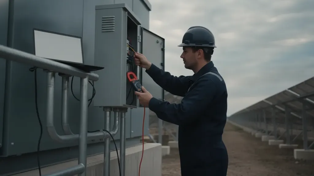
Every point the utility reads or writes needs a source-to-screen test: drive the value at the field device, confirm it at the control center, then confirm the acknowledgment path back. Gateway-only checks will pass points that are scaled wrong one hop downstream.
IEEE 1815 defines the DNP3 protocol used for most utility control-center and substation links, and the IEEE Standards Association catalog entry for IEEE 1815 is the reference to name in the test plan. Work the point list as a contract: analog inputs and outputs, binary inputs and outputs, scaling factors and engineering units, reporting deadbands, class assignments, unsolicited response behavior, and quality flags. Controls need select-before-operate verified along with the echo that tells the operator a setpoint was accepted rather than silently clamped. Time sync belongs in the same pass, since sequence-of-events analysis is only as good as the clock, and traceable time sources from NIST anchor that chain. Sites that bridge protocols internally should test the mapping layer too, which our OPC UA solar SCADA integration guide walks through, and weather sensor telemetry deserves the same scrutiny during solar meteorological station commissioning. Solar power plant controller commissioning is where those mappings are either signed off or inherited as latent defects.
How FAT and SAT expose scaling, latency, and failover defects in solar power plant controller commissioning
Factory acceptance testing runs the real controller logic against a simulated plant, so it catches point map and arithmetic errors cheaply. Site acceptance testing runs the same scripts against live inverters, meters, and comms paths, which is the only place latency and failover behavior become real.
Scaling defects hide in unit mismatches: a point published in kilowatts and consumed as megawatts, a raw integer range mapped to the wrong span, or a reactive point with inverted sign at one end. Inject minimum, midpoint, and maximum values at the source and read them at the destination, because the midpoint exposes a wrong offset that full-scale testing misses. On a 150 MW plant REIG commissioned in Cabarrus County, North Carolina in 2024, that exact midpoint check caught a reactive power point reporting in the wrong engineering units before SAT began, which would have read as a capability curve violation at the utility handoff if it had gone untested. Latency testing needs timestamps from one clock at each hop: utility command, gateway, controller, inverter, and meter response. Record the round trip instead of inferring it. Failover testing covers redundant controller switchover under load, dual communication paths, gateway restart, and loss-of-poll timers. The honest version of that test pulls cables while setpoints are active, since a standby controller that takes over with stale setpoints is a curtailment event waiting to happen. Solar power plant controller commissioning that skips the failover case tends to discover it during a real outage instead.
What records support utility witness testing and commercial operation
Witness tests move quickly when the package is already assembled: signed test procedures with pass criteria, an as-left point list, time-stamped trends for each setpoint step, controller configuration and firmware versions, meter calibration certificates, and a deviation list with closure evidence.
Two record sets matter past the witness day. The first is model validation data. NERC identifies accurate inverter-based resource performance data as necessary for ride-through evaluation and model validation, so trends captured during testing become baseline evidence for the plant model, and NERC publishes the assessments that explain why. The second is disturbance monitoring capability under PRC-028-1, which depends on configuration that commissioning should have verified rather than assumed. Cybersecurity baselines belong in the same binder, since the controller and its gateways fall in scope for controls described by the NIST Cybersecurity Framework. Interconnection milestones and the filings behind them are tracked at FERC, and the study work that set the plant limits is covered in our solar grid interconnection study guide. Keep the solar power plant controller commissioning package versioned, because firmware changes after commercial operation invalidate parts of it.
Sequencing solar power plant controller commissioning around utility witness tests
Sequence the work so each test has its prerequisites in place: protection settings loaded, revenue metering calibrated, communications proven, and enough inverter blocks energized to reach the output a given test needs. Witness windows are hard to reschedule, so hold points protect the schedule.
A workable order runs point-to-point checks before energization, control path and acknowledgment tests once the gateway is live, limited-capability setpoint tests as blocks come online, and full capability tests when irradiance and availability allow. Partial-output tests still carry weight, as long as the record states the conditions. Build in a retest rule as well: any change to controller firmware, point map, or inverter firmware reopens the affected tests. Integration material from the Department of Energy Solar Energy Technologies Office helps align owner, EPC, and utility expectations before the witness date is set.
Frequently asked questions
How long does solar plant controller commissioning usually take?
Schedule by discovery risk, not by script count. Factory acceptance testing usually runs several days against a simulated plant, while site acceptance testing stretches across the energization sequence because active and reactive tests need irradiance and available inverter blocks. Solar power plant controller commissioning slips when a mis-scaled telemetry point or a failed redundant link sends the team back to the vendor mid-campaign. Owners who want a defensible plan should read the utility-scale PV integration material published by the Department of Energy, then write hold points into the EPC schedule instead of assuming a fixed duration.
What is the difference between FAT and SAT in solar power plant controller commissioning?
Factory acceptance testing exercises controller logic against a simulated plant at the vendor site, which is the cheapest place to find point map errors, bad scaling, and logic that mishandles a mode transition. Site acceptance testing repeats the same scripts against live inverters, real meters, and the production communication path, so it is the first test that measures true round-trip latency and proves redundant controller failover. Treat FAT results as a prerequisite for mobilization rather than as evidence of site performance. The automation standards library maintained by the International Society of Automation is useful background when writing both procedures.
Is DNP3 required for utility telemetry on a solar plant?
The utility specifies the protocol, and in North America that specification is usually DNP3. IEEE 1815 defines the DNP3 protocol, and that standard is the reference to name in the point list and the test plan. Inside the substation, IEC 61850 often carries protection and measurement traffic, and plant-level integration may run OPC UA, so many sites test two or three protocol boundaries rather than one. Whatever the mix, the acceptance criterion stays the same: the value the utility operator reads matches the value the field device published, with correct units and quality flags. The IEC standards catalog documents the 61850 series.
How do I prove reactive power setpoints are accurate at the point of interconnection?
Measure at the point of interconnection meter, not at the controller screen. Confirm sign convention and polarity before closing the loop, then sweep reactive setpoints across the capability curve at several active power levels, logging inverter headroom at each step. Repeat near maximum irradiance, where reactive capability is most constrained, and capture time-synced trends so the utility can see response time and steady-state error. Grid integration research from NREL explains how plant-level reactive capability is characterized, which helps reconcile a capability curve on paper with what the inverter fleet delivers in the field.
What should the plant controller do if it loses the utility communication link?
The interconnection agreement and the utility specification define it, so commissioning verifies the defined behavior rather than inventing one. A common pattern holds the last valid setpoint for a defined timer, then falls back to a safe default limit or power factor, raises an alarm, and logs the transition. Test it by pulling the link while setpoints are active, and test recovery too, since a controller that resumes with stale commands becomes its own event. Reliability guidance and standards published by NERC compliance programs are the backdrop for both the fallback design and the records the utility will ask for.
What commissioning records does the utility keep after witness testing?
Expect the utility to retain signed test sheets with pass criteria, the as-left point list, time-stamped trends for each setpoint step, meter calibration certificates, and controller configuration and firmware versions. Owners should keep the same package plus the deviation list and its closure evidence, because disturbance monitoring and reporting duties for inverter-based resources under NERC PRC-028-1, effective April 1, 2025, depend on configuration that commissioning verified. Utility-scale project delivery guidance collected by SEIA helps align what the EPC hands over at substantial completion with what the owner needs to maintain the plant model.