
Solar substation breaker failure protection: testing field guide
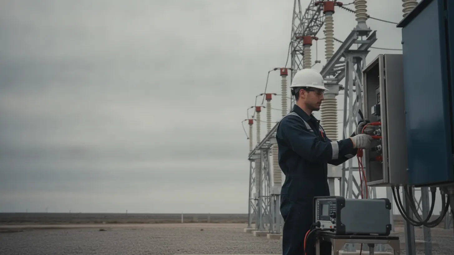
ANSI device 50BF is the only protection element in a substation that assumes the breaker in front of it has already failed. Set its timer two cycles too long and a stuck breaker holds a fault on the collector bus; set it two cycles too short and a healthy clearing operation trips the whole bus. A solar substation breaker failure protection scheme lives in that margin, and IEEE C37.119 defines how to size it.
How does solar substation breaker failure protection operate in a substation?
The scheme watches for one condition local protection cannot handle: a trip command issued, and current still flowing. A solar substation breaker failure protection relay arms a timer on breaker failure initiate, checks a current detector and the breaker position contact, then trips every adjacent source if the fault survives that timer.
Breaker failure initiate comes from the trip output of the primary element, not from a fault detector. Line distance, transformer differential, and bus differential relays all assert initiate when they command a trip. The scheme then drives two outputs: a retrip back to the same breaker through a separate trip coil, and after the timer expires, a backup trip to every breaker feeding the bus. Device numbering follows the IEEE C37.2 standard device function numbers, and the logic follows the IEEE C37.119 application guide for breaker failure protection.
Current, not position, decides the outcome. A 52a contact can report open while the interrupter still carries an arc, so the current detector supervises the timer. On collector substations this matters because inverters are current limited: fault contribution sits near rated output rather than the multiples a synchronous machine delivers, a behavior documented by NREL inverter-based resource research. Set the detector above maximum load unbalance and below the lowest contribution the plant can produce, then write the irradiance assumption into the settings file. Our NERC planning guide for grid-forming inverters covers the system side of that behavior.
Which ANSI 50BF elements and timers should engineers configure?
Five objects carry the scheme: the breaker failure initiate input, the 50BF current detector, the 62BF timer, the retrip output, and the 86 lockout that latches the bus trip. Each one has a separate test case, and each one has a setting that depends on the breaker in front of it.
| Scheme object | ANSI reference | What it must do | Setting basis |
|---|---|---|---|
| Breaker failure initiate | Per initiating relay | Assert on every trip command from line, bus, and transformer elements | Trip output contact or GOOSE dataset, one per element |
| Current detector | 50BF | Confirm current is still flowing after the trip command | Above maximum unbalance, below minimum inverter contribution |
| Timer | 62BF | Allow the breaker its rated clearing time before backup action | Interrupting time plus detector dropout plus logic plus margin |
| Retrip | Second trip coil | Try the same breaker again on an independent coil and DC branch | Zero or short delay, separate output contact |
| Bus lockout | 86 | Latch the backup trip to all bus sources and block reclose | Manual or supervised reset, with position reported in SCADA |
A solar substation breaker failure protection timer is a sum, not a preference: breaker interrupting time, current detector dropout, relay logic and output time, plus margin. The worked example below adds those terms at 60 Hz. Derive your own from the breaker nameplate and the relay instruction manual rather than copying a value from another plant.
Coordinating solar substation breaker failure protection with bus and transformer protection
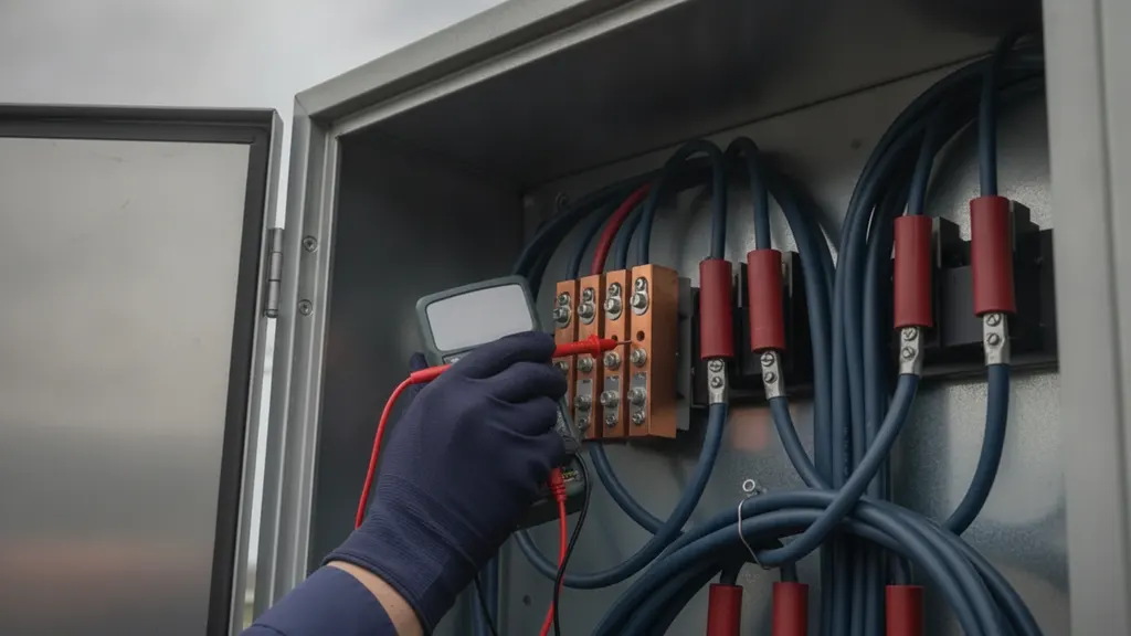
Coordination is a matrix exercise. A solar substation breaker failure protection scheme has to trip the bus zone feeding the failed breaker, send transfer trip to the remote line end where needed, and do neither of those things when the primary element clears normally.
Build the matrix before any wiring. Rows are initiating elements; columns are outputs: bus lockout, adjacent breaker trip coils, the transfer trip channel, and the SCADA alarm point. Where the bus sits inside a differential zone, the backup trip must open the same breakers that zone would open, and transformer backup needs its own row because the high side breaker may be the failed device. Our guide to transformer differential protection under IEEE C37.91 covers that zone boundary.
If outputs travel as GOOSE messages under the IEC 61850 substation communication standard series, publish the breaker failure trip in its own dataset with a short retransmission interval, and test the subscription rather than only the publisher. Hard contacts and GOOSE can coexist, but the matrix has to state which path carries each trip.
What secondary injection tests prove the trip matrix works?
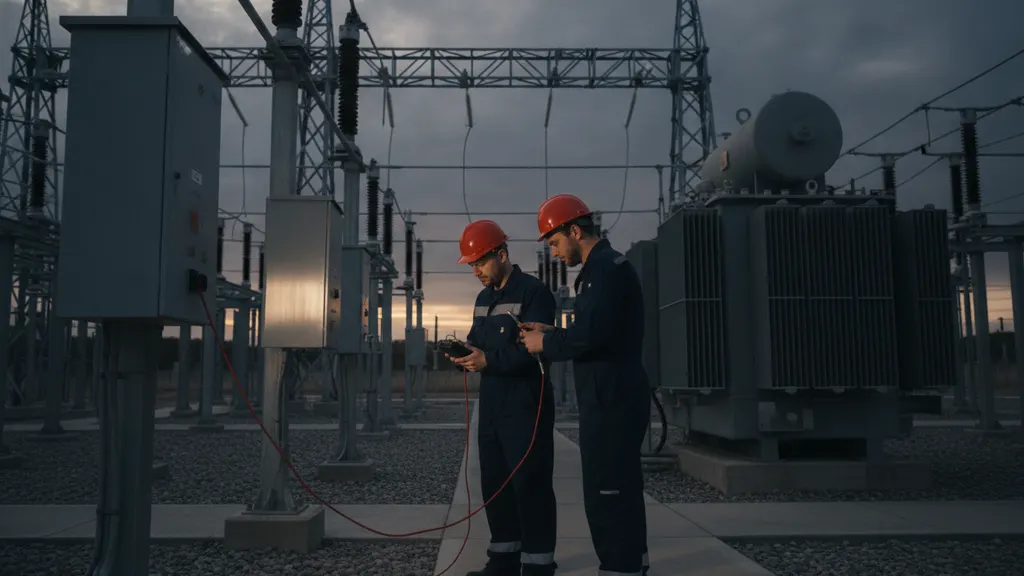
Pickup tests prove the element. Only injection with the trip outputs live proves the scheme. Inject into the primary relay, let it assert breaker failure initiate, hold current past the timer, then watch which contacts close and which lockout latches.
Scope the work from the trip matrix. A solar substation breaker failure protection scheme is verified when every initiating element has been injected, every output proven at the terminal block, and the timer measured rather than assumed. The coordination requirement in the NERC PRC-027 protection system coordination standard applies to protection systems on applicable transmission facilities, and testing practice is covered by EPRI transmission protection research. Record as-found and as-left values for both.
The injection sequence above exists because of a specific miss. At a 180 MWac project in Pecos County, Texas that REIG commissioned in March 2023, I watched a retrip test pass on the test sheet when it should not have: the primary trip coil cleared the fault during the same injection pulse meant to prove the redundant coil, so the breaker opened on schedule even though that second coil never fired. We only found the dead coil because the sequence of events record showed one mechanical operation against two trip commands, not two. That plant now gets its own column in the test sheet for each coil, proven on a separate pulse, because a passing timer does not mean every path behind it worked.
Test sequence for solar substation breaker failure protection
- Primary element injection with trip outputs live, confirming breaker failure initiate asserts.
- Timer measurement with current held past expiry, logging measured value against setting.
- Dropout case: current removed before expiry, proving no backup trip occurs.
- Initiate asserted with no current, proving the detector blocks the timer.
- Current present with no initiate, proving no spurious output.
- End-to-end output check to each adjacent breaker and the transfer trip channel.
| Injected condition | 50BF detector | Expected output |
|---|---|---|
| Trip asserted, current persists | Picked up | Retrip, then bus lockout 86 |
| Trip asserted, breaker clears | Dropped out | No backup trip |
| Initiate asserted, no current | No pickup | 62BF timer blocked |
| Current present, no initiate | Picked up | No output |
Our protection relay testing guide for solar substations covers test set configuration and injection sequencing in more depth.
Which SCADA events support solar substation breaker failure protection analysis?
The relay records prove what the scheme did; the SCADA log proves what the operator saw. For solar substation breaker failure protection, retain the initiate assertion, detector pickup and dropout, timer expiry, retrip output, lockout operation, and every breaker position change, all on one time base.
Resolution decides whether the record is usable. A one second scan class cannot order events inside a six cycle window, so map these points as event-driven with millisecond stamps rather than polled analogs, and keep oscillography in COMTRADE form beside them. Time quality depends on the clock chain, which should trace back to a reference of the kind maintained by the NIST Time and Frequency Division. Our guide to IEEE 1588 PTP time synchronization for solar SCADA covers the distribution side. Set retention in months, not days.
Commissioning records for solar substation breaker failure protection
These records are the deliverable a utility witness keeps on file: the as-left settings file with its version, the injection test sheets with measured timer values, the trip matrix verification table, and the SCADA point list showing where each event lands.
Keep the settings file under version control with the firmware revision recorded next to it, because a relay upgrade can change logic processing order. Tie each test sheet to the matrix row it proves. Reliability material published through US Department of Energy grid reliability resources and the coordination obligations in PRC-027 both assume this paper trail still exists years later. A workable handover structure is described in our guide to the solar SCADA commissioning witness pack.
Frequently asked questions
What does ANSI 50BF actually do in a substation?
Device 50BF is backup logic for a trip that has already been issued. When a primary relay commands a trip, it also asserts breaker failure initiate, which starts a timer. If current is still flowing when that timer expires, the scheme trips every other breaker feeding the same bus and usually sends transfer trip to the remote line end. The device number comes from IEEE C37.2, and application practice is set out in the IEEE C37.119 application guide. It never replaces the primary element; it covers the case where the primary element worked and the breaker did not.
How long should a breaker failure timer be set?
Add the terms rather than pick a number. The budget is breaker interrupting time from the nameplate, dropout time of the current detector, relay logic and output time, and margin covering measurement error and relay scatter. Interrupting time is published under the rating structure in the IEEE C37.04 circuit breaker rating standard, so start there instead of a default in the relay template. Then check the result against bus and transformer backup elements so the scheme still clears inside the time the interconnection study assumed for that fault.
Does breaker failure protection work if the inverters limit fault current?
It works, but the current detector needs a pickup based on the plant rather than a textbook multiple of load. Inverter-based resources hold fault current near rated output instead of delivering the large contribution a synchronous generator does, a behavior documented across the NREL utility-scale PV research program. Pick a setting above maximum unbalance and below the lowest contribution the plant can supply at the irradiance where it still runs, then record that assumption in the settings file. On the high side of a collector transformer, the grid source also feeds the breaker.
Can I rely on factory settings instead of testing breaker failure protection at commissioning?
No. Factory settings prove the relay, and solar substation breaker failure protection is wiring, lockout contacts, GOOSE subscriptions, and SCADA mapping. Every initiating element needs an injection that drives real trip outputs, with as-left contact states recorded. Plan the work as an isolated activity and follow the rules in OSHA electrical safety standards, because live trip circuits and open current transformer secondaries are the two hazards on this test. Witness inspectors usually ask for the sheet showing the backup trip reached each adjacent breaker, not only that the timer picked up.
What is the difference between retrip and backup trip?
Retrip is a second attempt at the same breaker, usually through the redundant trip coil, issued as soon as breaker failure initiate asserts or after a very short delay. Backup trip is the bus clearing action taken after the 62BF timer expires, and it opens every other source to the bus. Retrip costs nothing in selectivity and sometimes saves a bus outage caused by a failed trip coil or a lost DC branch, which is why protection research programs such as EPRI transmission protection research treat dual coil supervision and retrip as companion practices.
Which records does a utility ask for after a breaker failure event?
Expect a request for the sequence of events with millisecond stamps, oscillography from both the primary and the backup relay, breaker auxiliary contact transitions, the lockout operation, and the SCADA alarm log on the same time base. The value of all of it depends on time quality, so the substation clock chain needs a traceable reference of the kind described by the NIST time and frequency programs. Keep the raw files rather than screenshots, and keep them long enough to survive a utility review cycle that often starts months after the event.