Solar DAS commissioning: irradiance and weather QA standards
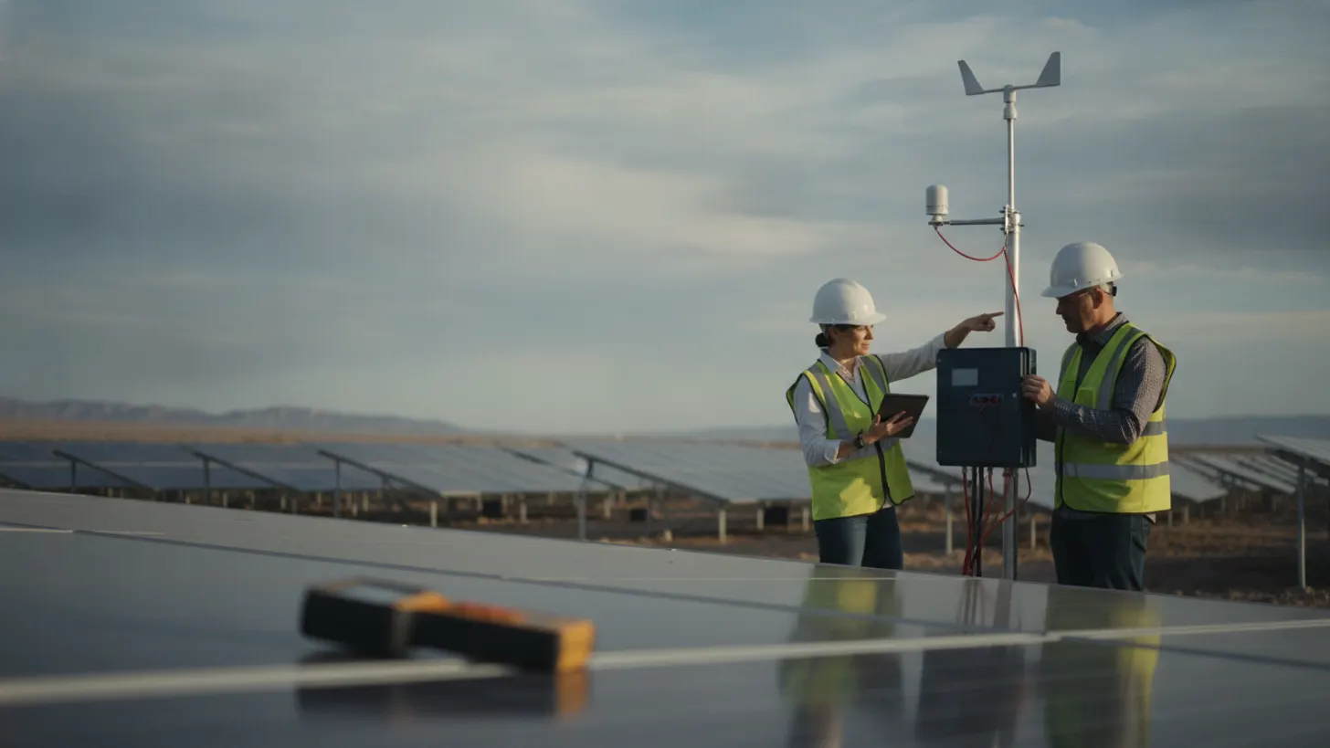
Solar DAS commissioning fails more often at the weather station than at the inverter. Field data from NREL’s best practices handbook for solar resource data shows pyranometer mounting and shading errors account for over 30% of first-year irradiance discrepancies on utility-scale plants. If the data acquisition system reports clean ambient temperature but the back-of-module thermistor reads 4°C low, the performance ratio will look healthy while modules degrade. Get the meteorological subsystem right at handover, or spend the next decade fighting ghost underperformance claims.
Why solar DAS commissioning starts at the weather station
The performance ratio of a utility-scale solar plant is only as honest as its meteorological inputs. Solar DAS commissioning that skips a rigorous weather and irradiance audit ships a plant with hidden basis risk. Lenders, EPCs, and O&M teams all reference the same set of irradiance and temperature streams to settle availability claims, calculate performance ratio, and trigger curtailment events.
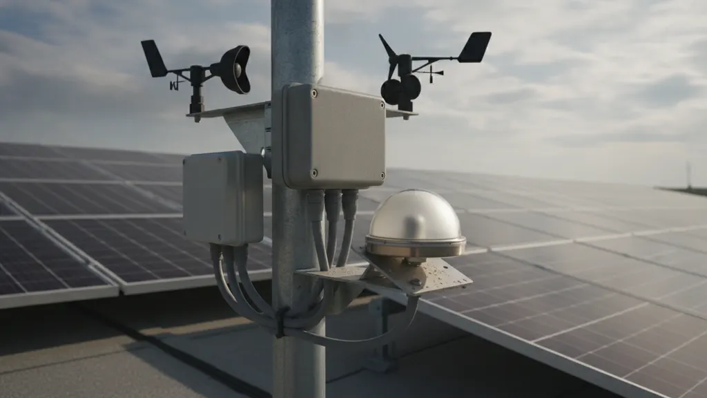
The IEC 61724-1:2021 standard for photovoltaic system performance monitoring distinguishes two monitoring classes, Class A and Class B. Class A is the only one acceptable for utility-scale acceptance testing. It requires two thermopile pyranometers per array, redundant ambient and module temperature sensors, a tipping-bucket rain gauge, a wind sensor at hub height, and traceable calibration documents for every instrument.
A team that treats the met station as a checkbox rather than a calibrated subsystem signs off on a plant whose data layer will be argued over for the asset’s full operating life. That finding sits at the center of the EPRI photovoltaic performance research program: weather QA at handover predicts performance dispute frequency over the next decade. See our breakdown of SCADA architecture for utility-scale plants for the upstream design choices that constrain met station options.
For a closer look at this, see Solar SCADA commissioning: building the utility witness pack.
For a closer look at this, see Solar DC cable insulation testing: HIPOT and megger commissioning guide.
Pyranometer calibration during solar DAS commissioning
Pyranometers drive revenue on a utility-scale plant. A 2% calibration drift on a 100 MW project translates to roughly $80,000 per year in misallocated performance credits at typical PPA pricing. Solar DAS commissioning teams should reject any pyranometer arriving on site without a current ISO 9847 outdoor calibration certificate issued within the last 12 months.
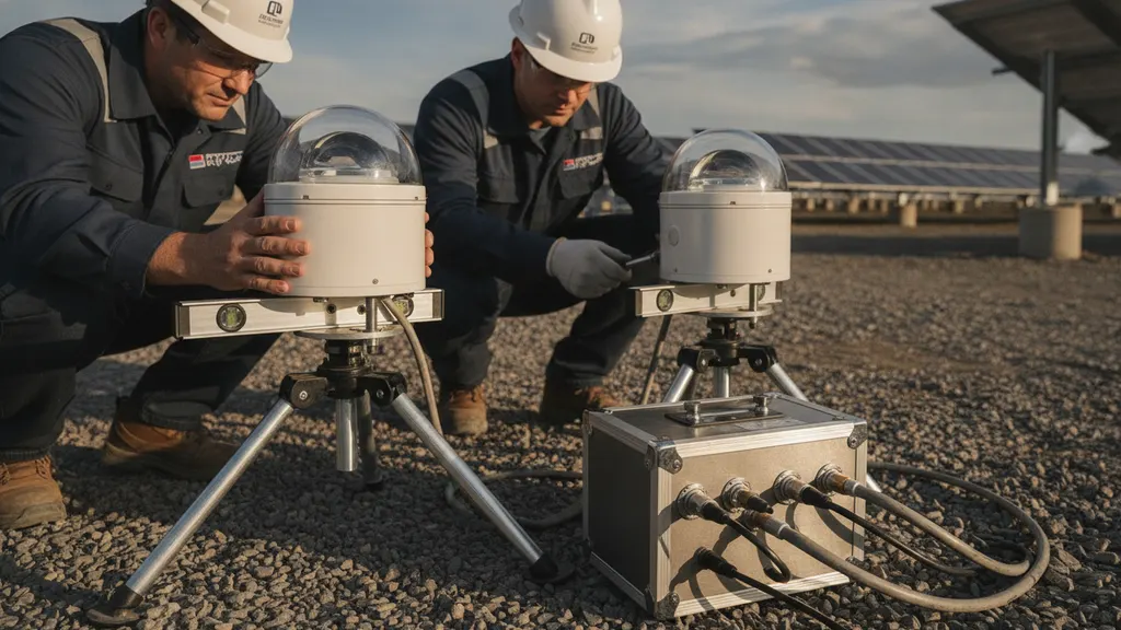
Mounting matters as much as the certificate. NREL’s pyranometer mounting and ventilation guidance states that mast tilt exceeding 1° from level introduces global horizontal irradiance errors of up to 2% on a clear day. Heated and ventilated pyranometers cut thermal offset by 80% compared with non-ventilated installations, which matters most at dawn, dusk, and during morning dew burn-off.
A clean handover package contains pyranometer serial numbers, calibration certificates, ISO 9847 traceability to a NIST-referenced reference cell, and a 14-day baseline comparison between paired instruments. Pairs that drift more than 1.5% over those two weeks fail the test and either get re-calibrated or replaced before the substantial completion certificate is signed. For bifacial plants, a rear-side pyranometer is now standard, with separate calibration certificates and an independent data channel into the SCADA historian.
Ambient and back-of-module temperature sensor QA
Module temperature drives the temperature-corrected performance ratio. A 4°C systematic error on back-of-module thermistors will shift reported PR by roughly 1.5%, the difference between hitting and missing a 95% PR guarantee. Solar DAS commissioning teams should specify RTD Class A sensors or thermistors with documented ±0.5°C accuracy across the 0°C to 80°C range, per IEC 61724-1 Annex C.
Sensor placement determines whether the measurement is honest. The thermistor must be bonded to the back of a representative module with thermally conductive epoxy, not taped or zip-tied. The bond line should be inspected with an IR camera at commissioning to confirm no air gap. DOE guidance on PV system performance monitoring recommends sampling at least three modules per inverter block to capture spatial temperature variance from edge-effect cooling.
Ambient temperature sensors belong in a Stevenson screen or aspirated shield, mounted 2 meters above ground over native vegetation rather than gravel, asphalt, or the project access road. Mounting an ambient sensor over heat-soaked ballast adds 3°C to 5°C of bias by mid-afternoon, which propagates into every soiling calculation, every degradation rate study, and every settlement statement for the asset’s life.
Wind speed and humidity validation on utility-scale plants
Wind data feeds the convective cooling term in the PR calculation and triggers high-wind stow events on single-axis trackers. A wind sensor mounted in the lee of a row, or behind a substation transformer, will under-read by 20% to 40%. Solar DAS commissioning teams should locate the primary anemometer per NREL Class A measurement guidance for utility-scale plants, at a height of 3 m to 4 m above the tracker top-of-stow, with at least 10 rotor diameters of clear fetch in the prevailing wind direction.
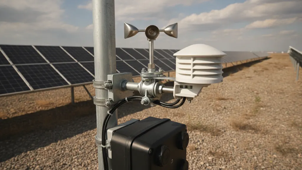
Ultrasonic anemometers outperform cup anemometers because they have no moving parts to ice up, no bearings to wear, and no dead-band at low wind speed. The commissioning team should validate the anemometer against a co-located reference for 14 days and reject the install if the regression slope drifts more than 5% over that window.
A capacitive RH sensor that has not been replaced or recalibrated in 24 months will read 8% to 12% high in coastal sites, per ISA process measurement standards. The commissioning specification should require annual RH sensor replacement, with the first 12-month replacement included in the EPC scope. Pair this with the operating discipline outlined in our O&M best practices for utility-scale solar.
Soiling stations and reference cells during solar DAS commissioning
Soiling stations quantify the gap between expected and actual energy yield from dust, pollen, and mineral deposition. Solar DAS commissioning that skips soiling validation hands the O&M contractor an unsolvable problem: prove the cleaning schedule is correct without baseline data. The soiling station should consist of two adjacent reference cells, one cleaned daily and one left exposed, with current measurement on both at 1-second resolution.
The cleaned reference cell defines the loss-free baseline. The soiled reference cell defines the actual loss rate. The ratio yields soiling loss as a percentage, which the SCADA system should log every 5 minutes and the O&M team should review weekly. Per IEC 61724-1, the soiling station must include both reference cells calibrated to the same secondary standard, plus a wash station with deionized water.
Reference cells should be matched to the module technology on the plant. A polycrystalline reference cell on a monocrystalline plant introduces spectral mismatch errors of 1% to 3% across the day. IEEE 1547-2018 interconnection standards reference the same matched-technology principle on the grid side. Commissioning teams should require the cell manufacturer’s spectral response curve in the handover package and run a 14-day clean-baseline comparison before signing the station off as production-ready. This data flows directly into PV performance ratio guarantees and lender reporting.
Data validation rules every solar DAS commissioning checklist must include
Sensor accuracy at handover decays without automated QA flags. Solar DAS commissioning programs should configure the SCADA historian to flag stale signals, frozen signals, out-of-range signals, and inter-sensor disagreement before those signals reach the performance ratio calculation. The table below summarizes the QA rules every met station should pass at acceptance.
| Channel | QA rule | Threshold | Action on fail |
|---|---|---|---|
| Pyranometer pair | Inter-sensor delta | >3% over 1 hour | Soft flag |
| Pyranometer | Night-time clamp | >5 W/m² 23:00 to 05:00 | Soft flag |
| Ambient temp pair | Drift between sensors | >0.5°C over 24h | Hard flag |
| Back-of-module RTD | Range check | <−20°C or >85°C | Hard flag |
| Wind sensor | Stuck signal | No change over 10 min daytime | Hard flag |
| Soiling reference | Cleaned-vs-soiled ratio | <0.85 sustained 24h | O&M alert |
The historian should write QA flags as a parallel channel rather than overwriting the raw value. Operators need to see both the raw reading and the QA verdict to triage instrument problems quickly. NIST calibration traceability guidance recommends preserving raw channels for the asset’s full operating life, with QA logic versioned in source control so any reanalysis can replay historical decisions.
The commissioning report should include the QA rule set, version hash, and a 30-day flag report showing which sensors triggered which rules during trial operation. Plants that ship without this discipline accumulate years of dirty data that the next O&M contractor will refuse to inherit. The independent engineer’s acceptance protocol typically requires all of the above before substantial completion is signed.
Frequently asked questions
How often should pyranometers be recalibrated on a utility-scale plant?
Per IEC 61724-1:2021, thermopile pyranometers in Class A monitoring systems should be recalibrated every 12 months against a Class AA or Class A reference instrument with ISO 9847 traceability. Lender requirements often tighten this to every 6 months for the first two years of operation, after which a stable site can move to annual. Photodiode pyranometers, sometimes used as secondary measurements, should be calibrated every 6 months because their spectral response degrades faster. The NREL data acquisition and monitoring report for PV plants documents typical drift rates by sensor class to help teams set a defensible schedule.
What does a solar DAS commissioning report need to include?
A defensible report contains: instrument serial numbers and calibration certificates, mounting inspection photos with timestamps, 14-day paired-sensor baseline comparisons, IR images of back-of-module thermistor bonds, the SCADA QA rule set with version hash, a 30-day flag report from trial operation, and traceability to NIST or equivalent national standards for every measured quantity. The handover should also include the soiling station baseline, the wind sensor regression against a reference, and a signed sign-off page from the independent engineer who witnessed the validation. Without this package, the asset owner cannot defend the performance ratio against a lender audit.
What is the minimum monitoring class for utility-scale solar?
IEC 61724-1:2021 Class A is the standard for utility-scale plants over 5 MW. Class A requires redundant pyranometers, redundant module and ambient temperature sensors, a wind sensor at hub height, a rain gauge, and traceable calibration on every instrument. Class B is intended for portfolio-level monitoring on smaller commercial installations, and Class C is for indicative residential systems. A lender financing a utility-scale plant will almost always require Class A in the EPC specification, and the independent engineer will not sign substantial completion if the as-built met station does not meet that class.
How do soiling stations affect the performance ratio guarantee?
Soiling loss is a separate line item in most modern PR guarantees, calculated from the soiling station’s cleaned-versus-soiled reference cell ratio. If the soiling station was not commissioned correctly, the EPC and the asset owner have no defensible way to allocate underperformance between equipment problems and module dust load. The result is years of dispute over who pays for marginal output gaps. The DOE solar operations and maintenance resources cover soiling station commissioning best practices, including the importance of establishing a clean baseline before treating soiling measurements as authoritative.