
Solar Data Acquisition System (DAS) Tagging: Units, Scaling, and QC for Utility-Scale PV
Solar Data Acquisition System (DAS) Tagging: Units, Scaling, and QC for Utility-Scale PV
In a utility-scale solar plant, your solar data acquisition system (DAS) is only as trustworthy as the “last mile” details: point naming, units, scaling, and quality control (QC). When those basics are wrong (or inconsistent), the symptoms show up everywhere—incorrect KPIs, failed performance reports, confusing alarms, and long troubleshooting loops that feel like “mystery data gaps.”
This article is for solar owners/operators, developers, EPCs, and O&M teams who want a grounded, commissioning-ready approach to solar data acquisition system (DAS) tagging. Specifically, you’ll learn how to define units, apply scaling without surprises, and validate signals end-to-end so your SCADA screens, historian data, and reports agree.
Solar data acquisition system (DAS) tagging: quick definitions (units, scaling, QC)
Before we get tactical, here’s what these terms mean in day-to-day project work.
- DAS tagging: the convention for identifying each data point (tag name), describing it (metadata), and ensuring downstream systems (SCADA/HMI, historian, reports) interpret it correctly.
- Units: engineering units that describe the quantity (kW, kWh, V, A, Hz, W/m², °C, m/s, %, etc.).
- Scaling: the math that converts a raw value (counts, register value, mA signal, vendor-specific encoding) into engineering units.
- QC (quality control): the test process and acceptance criteria that prove the tag is correct at every layer (device → network → SCADA/DAS server → historian → report).
At a systems level, a solar data acquisition system (DAS) includes sensors/instruments, signal conditioning, data logging/measurement, and communications—so each layer can introduce unit/scaling errors if it’s not documented and tested. Renesas’ DAS design note is a useful general reference for how conditioning, conversion, and throughput constraints shape reliable acquisition. Meanwhile, HeatSpring’s utility-scale PV DAS overview is a practical PV-oriented reference for typical equipment and why weather and metering signals matter during testing and operations.
Why solar DAS tagging mistakes are so expensive after COD
Tagging errors rarely look like “the DAS is down.” Instead, they look like:
- For example, power or energy values that are consistently off by 10x or 1000x,
- Additionally, irradiance values that are plausible but wrong (bad scaling, wrong sensor constant),
- Likewise, meter values that don’t match revenue-grade expectations (CT/PT ratios or register interpretation issues),
- Meanwhile, temperature or wind values that drift or flatline without obvious alarms,
- Finally, reports that disagree with SCADA screens (different scaling in different layers).
Fixing this after COD is costly because changes ripple through historian mappings, dashboards, performance models, alarm thresholds, and sometimes contractual reporting. For that reason, the most practical strategy is to treat unit/scaling and QC as commissioning deliverables—not “cleanup later.”
A solar data acquisition system (DAS) tagging deliverable: what your point list should contain
The point list (sometimes called a tag list or I/O list) should be more than tag names. In practice, it becomes the single source of truth that engineering, commissioning, and O&M can rely on.
Minimum fields for a solar DAS point list (recommended)
- First, include a tag name (unique and stable).
- Next, add a clear description (plain language).
- Then, define the asset hierarchy (plant/subsystem/device, e.g., Inverter 12, Meter Main, MET).
- Also, specify the signal type (analog, digital, counter, string, quality).
- Additionally, lock in the engineering units.
- Afterward, document the raw source (protocol + register/point ID + data type).
- Moreover, write the scaling definition (formula, multiplier/divider, offset, and any vendor-specific encoding notes).
- In addition, include the expected range (normal operating band + “sanity limits”).
- Likewise, record the update rate (poll interval or event-driven).
- Finally, define the QC test method (how you will prove it’s correct).
- As a result, capture historian requirements (archive yes/no, sample/avg, compression/deadband).
In addition, it helps to tie points to your hardware bill of materials (BOM) so field teams can verify sensors, transducers, and wiring match the design intent. For a practical example of how solar DAS scope is often framed around loggers, sensors, meters, and integration components, see this overview of DAS BOM elements from Nor-Cal Controls. (DAS BOM overview)
Solar DAS units: choose one “truth” and stick to it
Unit inconsistency is one of the fastest ways to break data trust. The fix is simple: define a plant-wide unit standard and apply it in every layer (device config, SCADA/DAS mapping, historian, reporting).
Common unit decisions that should be explicit in a solar data acquisition system (DAS)
- Power: kW vs W vs MW
- Energy: kWh vs Wh vs MWh (and whether the signal is an accumulating total or interval energy)
- Voltage/current: V, A (including whether values are line-to-line, line-to-neutral, phase, or average)
- Frequency: Hz
- Irradiance: W/m² (confirm sensor output and calibration factor)
- Temperature: °C vs °F (most utility-scale analytics assume °C)
- Wind speed: m/s vs mph
- Angles: degrees (tracker/mount positions)
- Power factor: unitless (often shown as PF, sometimes signed)
Practical rule
If an operator or analyst has to ask “is this kW or W?” more than once, the system is already costing time. Therefore, units should be visible in SCADA and encoded in your point list metadata so reports can’t “guess.”
Solar DAS scaling: where most “looks fine” signals go wrong
Scaling converts raw numbers into engineering units. In solar plants, scaling errors typically come from one of four places:
- Sensor/transducer math: for example, 4–20 mA mapping, sensor sensitivity, shunt/CT conversions.
- Protocol/register interpretation: signed vs unsigned integers, floating point formats, endianness, word order, or vendor-defined scaling registers.
- Multi-layer scaling: scaling applied in the device and again in the SCADA/DAS mapping (double-scaling), or applied nowhere.
- Ratio configuration: meter CT/PT ratios and scaling for engineering outputs.
Design guidance for acquisition systems emphasizes that analog front-end choices (amplification, filtering) and conversion resolution affect accuracy and reliability. Similarly, at the tag layer: if you don’t define scaling clearly, you can’t claim accuracy. (DAS design considerations)
Scaling pattern #1: linear scaling (multiplier + offset)
This is the most common case for sensors and some device registers.
EngineeringValue = (RawValue × Multiplier) + Offset
Examples:
- 0–10 V input representing 0–1000 W/m² (Multiplier 100, Offset 0)
- 4–20 mA representing -40 to 60 °C (Multiplier 6.25, Offset -65) depending on input card mapping
Scaling pattern #2: ratio scaling (CT/PT and similar)
For meters and some current/voltage measurements, the raw value may be “secondary” and needs conversion to primary using ratios. However, if these ratios are wrong, the data can be consistently wrong while still looking stable.
PrimaryValue = SecondaryValue × Ratio
Where the ratio may be CT ratio, PT ratio, or combined.
Scaling pattern #3: vendor-defined scaling registers or enumerations
Some devices provide:
- a value register and a separate scale register (e.g., exponent), or
- a raw value that must be interpreted based on a documented format.
In that case, scaling belongs in one layer (preferably where it’s easiest to audit and version-control). Also, document it in your point list as “source-of-truth scaling.”
A simple table to prevent the most common scaling failures
| Failure mode | What it looks like | Prevention |
|---|---|---|
| Double scaling | Value is off by constant factor (often 10x/100x/1000x) | Declare where scaling happens (device vs SCADA vs historian) and lock it |
| Wrong data type / endianness | Values jump wildly or look “random” | Document register type, signedness, word order; test with known references |
| Wrong ratio (CT/PT) | Stable but wrong by a constant factor | Verify CT/PT settings against drawings and field labels; include in QC plan |
| Units mismatch | kW displayed as W, or °F treated as °C | Unit standard + metadata enforced across SCADA and historian |
| Implicit scaling hidden in reports | Report disagrees with SCADA/HMI | Historian stores engineering units; reporting reads without extra transforms |
Solar data acquisition system (DAS) QC: prove the signal end-to-end
QC should verify three things for each critical point: (1) the value is right, (2) the unit is right, and (3) the timestamp and quality are right.
In practice, a solar DAS exists to provide comprehensive visibility and alerting across plant equipment and sensors, including MET instrumentation that supports acceptance testing and performance evaluation. As a result, QC is especially important for weather and metering points. (Utility-scale PV DAS context)
QC tiering: test depth based on risk
Not every tag deserves the same test effort. A practical approach is to define tiers:
- Tier 1 (must be perfect): revenue-grade meter points, POI/substation measurements, plant power, curtailment setpoints/limits, key inverter power and status, key MET points used in performance tests (GHI/POA, module temp, ambient).
- Tier 2 (important for availability): inverter fault detail, tracker stow/fault states, comms health, switch/UPS statuses, derived KPIs used in dispatching.
- Tier 3 (nice to have / informational): secondary diagnostics that do not drive contractual reporting or operations decisions.
End-to-end QC methods (choose what fits the point)
- First, use a reference comparison: compare DAS reading to a trusted reference (handheld meter, device local display, calibrated instrument).
- Next, run a stimulus test: inject a known signal (where safe and permitted) and confirm the value arrives correctly.
- Additionally, do a cross-system comparison: compare inverter-reported power to plant meter totals (with expected losses/tolerances).
- Meanwhile, apply range/sanity checks: enforce physics-based bounds (e.g., irradiance at night should be near zero; wind speed shouldn’t be negative).
- Finally, perform data completeness checks: confirm points are continuously recorded at expected intervals, with quality flags.
A practical QC checklist for a solar data acquisition system (DAS)
- Confirm the tag exists in SCADA/HMI and in the historian (if required).
- Verify engineering units match the point list.
- Check scaling by comparing against a trusted reference at two operating points (low and high, if possible).
- Make sure timestamps align (time sync) and quality flags behave during comms interruptions.
- Ensure alarm thresholds (if any) are in the same units as the displayed value.
- Record the test result, reference used, and pass/fail with date and tester initials.
Solar DAS tagging examples (units + scaling + QC) for common PV subsystems
Below are examples of how to document a tag so it’s auditable.
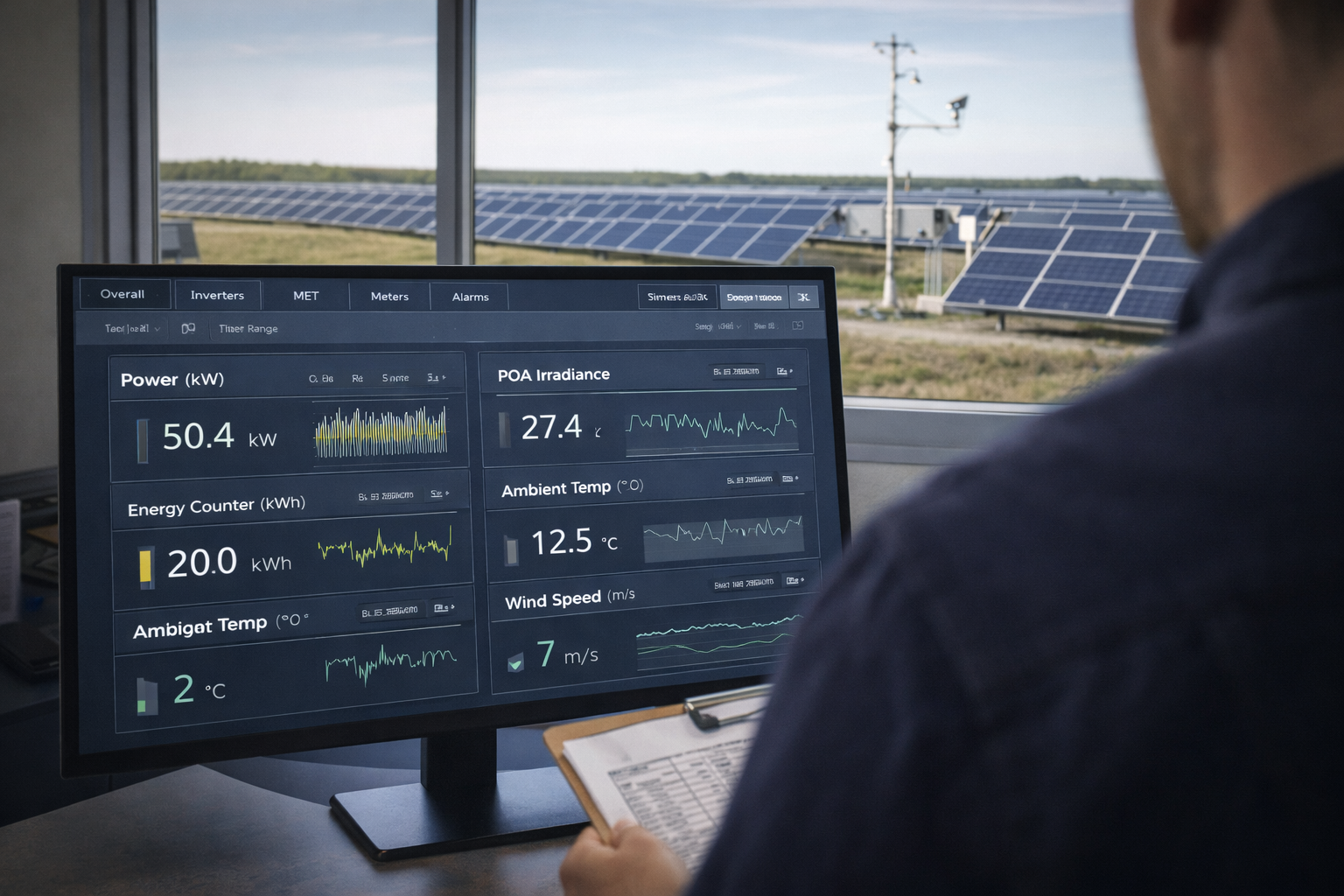
Example 1: POA irradiance (MET station)
- Tag: MET01_POA_Irradiance
- Units: W/m²
- Scaling: based on sensor output + input module scaling (document sensor sensitivity or transmitter mapping)
- Expected range: 0–1300 W/m² (site-dependent)
- QC: compare against MET station display or logger raw channel; validate night-time baseline near zero; validate midday reasonableness relative to clear-sky expectations
Example 2: revenue meter real power
- Tag: MTR01_kW
- Units: kW
- Scaling: confirm register type and that CT/PT ratios are correctly configured (or applied in mapping if not configured in device)
- Expected range: -Pmax to +Pmax depending on import/export rules (site-specific)
- QC: compare against meter front panel or utility test set data (as applicable); verify sign convention during known export/import conditions
Example 3: inverter AC power
- Tag: INV12_AC_kW
- Units: kW
- Scaling: confirm whether inverter provides kW directly or W, and whether register already includes scaling
- QC: compare to inverter local HMI; verify aggregation logic (sum of inverters vs plant meter) within expected tolerance
Historian and reporting: keep one source of truth for solar DAS tags
Many teams unintentionally create two sources of truth:
- SCADA shows engineering units with one scaling approach,
- historian stores raw values (or differently scaled values),
- reports apply additional transformations.
That’s a recipe for disputes and wasted time. Instead, use this practical standard:
- Historian stores engineering units (already scaled) whenever possible.
- Reports do not rescale—they calculate KPIs from consistent engineering-unit tags.
- All transforms are documented (e.g., any derived calculations) and version-controlled.
Documentation that prevents “tribal knowledge” operations
At handoff, a plant should not require “the one person who knows the tags.” The minimum documentation package that supports long-term ops includes:
- as-built point list (including units, scaling, ranges, and QC methods),
- QC test records (what was tested, how, and results),
- network and communications drawings (including key comms paths),
- alarm list with priorities and thresholds tied to units,
- a change log for tag modifications post-commissioning.
Where REIG fits: commissioning-ready solar data acquisition system (DAS) tagging
REIG’s integration approach is built around making plant data dependable from day one: a commissioning-ready SCADA + DAS stack, standardized deployments (including rugged RenergyWare enclosures/hardware configurations), and end-to-end verification that reduces rework and shortens the path to COD. Ultimately, the goal is fewer surprises during commissioning, and fewer “is it comms or is it equipment?” troubleshooting loops after handoff.
Action plan: implement a solar DAS tagging standard in the next 2–4 weeks
- Pick Tier 1 points (meters, POI, plant totals, key MET, key inverter power/status) and lock unit standards.
- Define where scaling lives (device vs SCADA mapping) and remove any double-scaling paths.
- Add expected ranges to the point list for fast sanity checks.
- Run end-to-end QC on Tier 1 points and document results.
- Confirm historian alignment (engineering units stored, sample intervals, and quality flags).
Conclusion: clean solar DAS tags are a reliability feature
A solar data acquisition system (DAS) is not “just data.” Instead, it’s the evidence you use to commission the plant, prove performance, and troubleshoot quickly for years. As a result, when units, scaling, and QC are done in a commissioning-ready way, your SCADA screens, historian, and reports match—and teams stop wasting time arguing with the data.
If you’re building a new plant or cleaning up recurring data quality issues, REIG can help you standardize a commissioning-ready tagging and validation approach across your SCADA + DAS stack—so your team can trust the data and move faster.
FAQ
What’s the difference between a DAS tag name and a point list?
A tag name is the identifier for one data point (for example, INV12_AC_kW). A point list is the structured dataset that defines every tag and its metadata—units, scaling, source register, expected range, historian settings, and QC method. In practice, the point list becomes the “source of truth” used by engineering, commissioning, and O&M.
Where should scaling be applied: in the field device, SCADA mapping, or historian?
The most important rule is to apply scaling in one place and document it. Many teams prefer scaling in the SCADA/DAS mapping layer because it’s easier to audit, version-control, and keep consistent across devices. If a device outputs engineering units natively (and that configuration is locked and documented), it can be fine to scale in the device—just avoid double-scaling downstream.
How do we QC a tag if we can’t safely inject a test signal?
Use reference comparisons and cross-checks. For example, compare inverter kW to its local display, compare aggregated inverter power to a plant meter within expected tolerance, and validate MET points with logger diagnostics and physics-based sanity checks (like near-zero irradiance at night). The goal is to prove the value, units, and timestamps are correct end-to-end without creating safety or warranty risks.
What tags are most likely to cause COD or performance-test problems if they’re wrong?
Revenue-grade meter points, POI/substation measurements, plant power and energy totals, curtailment limits, and the MET signals used in performance testing (POA/GHI irradiance and key temperatures) are typically the highest-risk. If those points have wrong units or scaling, performance calculations and acceptance testing can fail or require time-consuming rework. Make these “Tier 1” and QC them first.
How do we prevent SCADA screens and reports from disagreeing?
Standardize units and scaling at the source and ensure the historian stores engineering-unit values wherever possible. Reports should calculate KPIs from those same engineering-unit tags rather than rescaling inside a reporting tool. Finally, keep a change log: even small tag changes post-COD can silently break dashboards and analytics if they aren’t tracked.
Further reading
References
Next step
If you’re seeing unit/scaling inconsistencies, historian mismatches, or “mystery” data gaps during commissioning or after COD, REIG can help you implement a commissioning-ready solar data acquisition system (DAS) tagging and QC process—validated end-to-end, documented cleanly, and built to stay reliable in operations. Reach out to scope a practical plan that improves data trust without adding unnecessary complexity.


