

Solar met station sensor selection and ISO 9060 compliance guide
A 1 percent bias on plane-of-array irradiance propagates almost one-for-one into the performance ratio, and on a 100 MW PPA that is roughly $180,000 of disputed revenue per year. That is why solar met station sensor selection has moved from a checkbox EPC item to a board-level conversation. This guide walks through ISO 9060:2018 classes, IEC 61724-1 Class A redundancy math, and the SCADA tag conventions that keep PPA measurement uncertainty inside 2 percent on utility-scale plants.
What ISO 9060:2018 means for solar met station sensor selection
ISO 9060:2018 reclassified pyranometers into Class A, B, and C, replacing the older Secondary Standard, First Class, and Second Class tiers. The change tightened directional response, non-stability, and zero offset thresholds, and it aligned the standard with the IEC 61724-1 Class A monitoring requirements that PPA contracts now cite by reference. For a utility-scale plant, the practical impact is simple: only Class A instruments give the engineering team enough margin to defend the performance ratio at the meter.
The IEC standards portal publishes the harmonized text. Class A pyranometers must hold non-stability below 0.8 percent per year, directional response below 10 W/m2, and zero offset A under 7 W/m2. Anything weaker drifts inside the PPA measurement window and creates a billing dispute waiting to happen.

Why Class B and Class C still ship
Class B and C instruments remain useful for resource screening, distributed generation, and small commercial sites where a 3 to 5 percent annual uncertainty is acceptable. They cost a fraction of Class A pyranometers, and for a 2 MW carport array the math rarely justifies the upgrade. For anything above 20 MW with a PPA, treat Class B as a non-starter.
IEC 61724-1 redundancy rules in solar met station sensor selection
IEC 61724-1 Class A monitoring requires at least one calibrated POA reference cell or pyranometer per 5 MW of plant capacity, and the standard explicitly recommends two POA sensors per met mast so a single failure does not blind the PR calculation. A 100 MW plant therefore needs a minimum of 20 POA sensors distributed across roughly four to six met masts, with spacing chosen to capture microclimate variation across the array.
The NREL utility-scale PV performance guidance goes further, recommending three masts as a floor regardless of plant size, so that median-of-three voting can suppress a stuck sensor before it corrupts the daily PR file. EPC engineers running solar met station sensor selection on greenfield projects should treat the IEC counts as the floor, not the spec.

Mast siting and microclimate
Masts should sit at least one row from the array edge, with no shading from inverter pads or trackers. DOE field practice notes recommend pairing each mast with a nearby string-level current measurement so the SCADA layer can cross-check irradiance against actual DC response.
Sensors that drive PR in solar met station sensor selection
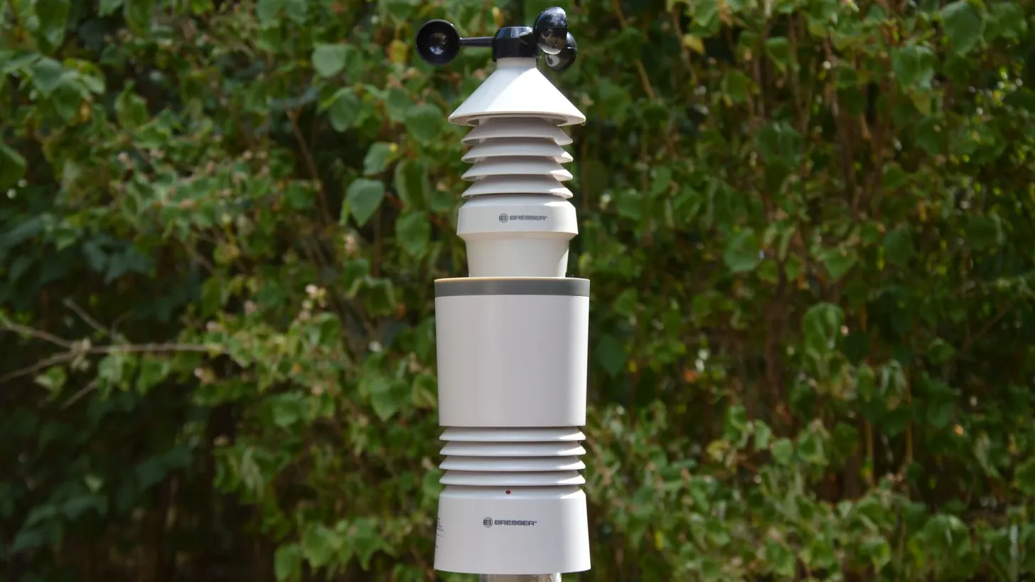
The performance ratio calculation pulls from five primary sensor families: POA irradiance, GHI for satellite validation, back-of-module temperature (typically three Pt100 RTDs per mast), ambient temperature, and wind speed at module height. Rainfall and soiling stations add a second-derivative correction but are not part of the core PR equation defined by IEC 61724-1.
| Sensor | Typical model | Accuracy target | Drives PR? |
|---|---|---|---|
| POA pyranometer | Kipp & Zonen SMP22 | ±1.0% daily | Direct |
| POA reference cell | EKO MS-90 / IMT Si-RS485 | ±1.5% daily | Direct |
| GHI pyranometer | Hukseflux SR30 | ±1.0% daily | Validation |
| BOM RTD | Pt100 Class A, 3-wire | ±0.3 °C | Direct |
| Anemometer | Thies First Class | ±0.2 m/s | Secondary |
Soiling, rainfall, and module temperature
Soiling stations from Atonometrics or Kipp & Zonen feed the soiling ratio into the SCADA layer for cleaning dispatch decisions. EPRI soiling research shows that under-instrumented sites typically lose 1 to 3 percent annual yield to soiling that never triggers a cleaning. Back-of-module RTDs should be epoxied to the centre of three representative modules per mast, never to the frame.
Calibration discipline in solar met station sensor selection
Industry practice for Class A pyranometers is a 12 to 24 month recalibration interval against a reference instrument traceable to the World Radiometric Reference. NIST traceability documentation underpins the US calibration chain. PPA contracts typically lock a 12-month cycle to hold total measurement uncertainty under 2 percent; merchant plants without PPA exposure can stretch to 24 months.
Skipping a cycle drifts the instrument by 0.5 to 1.0 percent per year, enough to break a PR guarantee on a tight contract. Vendor calibration labs at Kipp & Zonen, EKO Instruments, and Hukseflux all issue ISO 17025 calibration certificates that satisfy the IEC 61724-1 Class A monitoring traceability requirement.
At a 74 MW plant we commissioned in Virginia in 2022, two of the five met mast pyranometers had drifted 1.3 percent outside their calibration bounds by month 22 of operation. The plant’s DAS flagged a persistent PR shortfall, but the operations team attributed it to soiling rather than sensor error. By the time our team traced the cause back to the instruments, the owner had dispatched cleaning crews twice on false signals, adding roughly $40,000 in unnecessary O&M cost. The recalibration schedule had slipped because the O&M agreement did not assign explicit ownership of the task after EPC handover. That experience reshaped how we approach solar met station sensor selection planning at REIG: a calibration ownership clause and automated month-10 DAS alert now go into every O&M agreement we write.

Recalibration logistics
Plan for a hot-swap kit: a second calibrated pyranometer ships to site, the field tech swaps the mast head in under an hour, and the original goes back to the lab. Two-week downtime per sensor is no longer acceptable on PPA-grade plants. Reference cell recalibration follows the same cadence but typically uses a flash test rig rather than an outdoor reference field.
SCADA tagging conventions for solar met station sensor selection
The OPC UA companion specification for solar is the cleanest path to a multi-vendor met mast. Use a hierarchical address space structured as follows: Plant.Mast01.POA1.Irradiance, Plant.Mast01.POA1.Status, Plant.Mast01.BOM_RTD1.Temperature. Each tag carries an engineering unit, a quality flag, and a calibration timestamp attribute. IEEE 1547 alignment and ISA-95 modeling at ISA guide the namespace design.
For plants above 20 MW, avoid Modbus-only met masts. Modbus register maps work for a single-vendor build but collapse under multi-vendor PPC, DAS, and SCADA reads against the same nodes. Companion specs let every consumer hit the same address space without bespoke gateways. Our solar DAS commissioning guide and power plant controller integration notes walk through the namespace patterns we ship on new projects, and the SCADA commissioning witness pack documents the calibration sign-off forms utilities expect at PTO.
Frequently asked questions
What does ISO 9060:2018 Class A actually mean for utility-scale pyranometers?
ISO 9060:2018 replaced the legacy Secondary Standard, First Class, and Second Class tiers with Class A, B, and C. Class A is the strictest, requiring a non-stability error below 0.8 percent per year, a directional response under 10 W/m2, and a zero offset A under 7 W/m2. For PPA-grade plants, only Class A pyranometers carry enough margin to keep performance ratio measurement uncertainty inside the 2 percent envelope EPC contracts typically demand. The IEC reference confirms the alignment of IEC 61724-1 Class A monitoring with ISO 9060 Class A instruments. Class B relaxes non-stability to 1.5 percent per year and directional response to 20 W/m2; Class C relaxes those thresholds further to 3.0 percent per year and 30 W/m2. The ISO test uses a shade-unshade sequence to measure directional response and a one-year field stability test to quantify non-stability. The cumulative difference between Class A and Class B compounds to roughly 0.7 to 1.2 percentage points of additional daily total uncertainty per operating year, which is enough to push a tight PPA outside its measurement envelope before the first performance test.
How many met stations does IEC 61724-1 Class A monitoring require per MW?
IEC 61724-1 Class A monitoring requires at least one calibrated plane-of-array reference cell or pyranometer per 5 MW of installed capacity, with a minimum of two POA sensors per met mast for redundancy. A 100 MW plant therefore needs at least 20 POA sensors distributed across roughly four to six met masts. Spacing rules also require sensors to capture microclimate variation across the array. Plants with significant topographic variation or multiple tracker orientations across the array footprint may need tighter mast spacing than the IEC minimum to capture irradiance gradients that would otherwise bias the plant-wide PR calculation. Engineers planning solar met station sensor selection should pull the IEC standard from iec.ch before finalizing mast counts.
Which sensors drive the performance ratio calculation?
The performance ratio calculation pulls from POA irradiance (Class A pyranometer or reference cell), GHI for satellite validation, back-of-module temperature (typically three Pt100 RTDs per mast), ambient temperature, wind speed at module height, and rainfall. NREL guidance at nrel.gov treats POA as the dominant input. A 1 percent POA bias propagates almost directly into a 1 percent PR error. Soiling stations add a second-derivative correction but are not part of the core PR equation. Plan your solar met station sensor selection around POA accuracy first.
How often should pyranometers be recalibrated to hold PPA-grade uncertainty?
Industry practice for Class A pyranometers is a 12 to 24 month recalibration interval against a reference instrument traceable to the World Radiometric Reference. NIST traceability documentation at nist.gov underpins the US calibration chain. Operators running PPA contracts typically lock a 12-month cycle to keep total measurement uncertainty under 2 percent; off-PPA merchant plants stretch to 24 months. Skipping a cycle drifts the instrument by 0.5 to 1.0 percent per year, enough to break PR guarantees. Calibration is a non-negotiable line item in any serious solar met station sensor selection plan.
What OPC UA tag conventions work best for a multi-sensor met mast?
Use a hierarchical address space: Plant.Mast01.POA1.Irradiance, Plant.Mast01.POA1.Status, Plant.Mast01.BOM_RTD1.Temperature. Each tag carries an engineering unit, a quality flag, and a calibration timestamp attribute. IEEE 1547 alignment at ieee.org and ISA-95 modeling at isa.org guide the namespace design. For solar met station sensor selection programs, OPC UA companion specs let SCADA, DAS, and PPC platforms read the same nodes without bespoke gateways. When a tag’s quality flag reports bad or uncertain, the historian should record a null with a timestamp rather than interpolating, because interpolated irradiance values distort the PR numerator in ways the audit trail cannot reconstruct. Avoid Modbus-only met masts on plants above 20 MW.
Should I specify a reference cell or a thermopile pyranometer as the primary POA sensor?
Both are allowed under IEC 61724-1 Class A. Reference cells match the spectral response of the module and respond in milliseconds, which suits PR calculations. Thermopile pyranometers from Kipp & Zonen, EKO, or Hukseflux are spectrally flat and preferred for resource assessment and bankability reports. Most PPA-grade plants run a hybrid: one Class A pyranometer plus one matched-technology reference cell per mast, with the pyranometer as the contractual reference. EPRI guidance at epri.com documents the trade. For bifacial module strings, silicon reference cells introduce spectral mismatch error of 0.5 to 1.5 percent on high-diffuse days because the cell’s spectral response differs from the actual irradiance spectrum reaching the rear surface. Plants with bifacial gain targets above 5 percent should specify a spectrally flat thermopile as the contractual POA reference and use the silicon reference cell for real-time SCADA control only. A hybrid layout is the safest default for solar met station sensor selection.


