
Solar plant transformer commissioning: IEEE test plan for owners
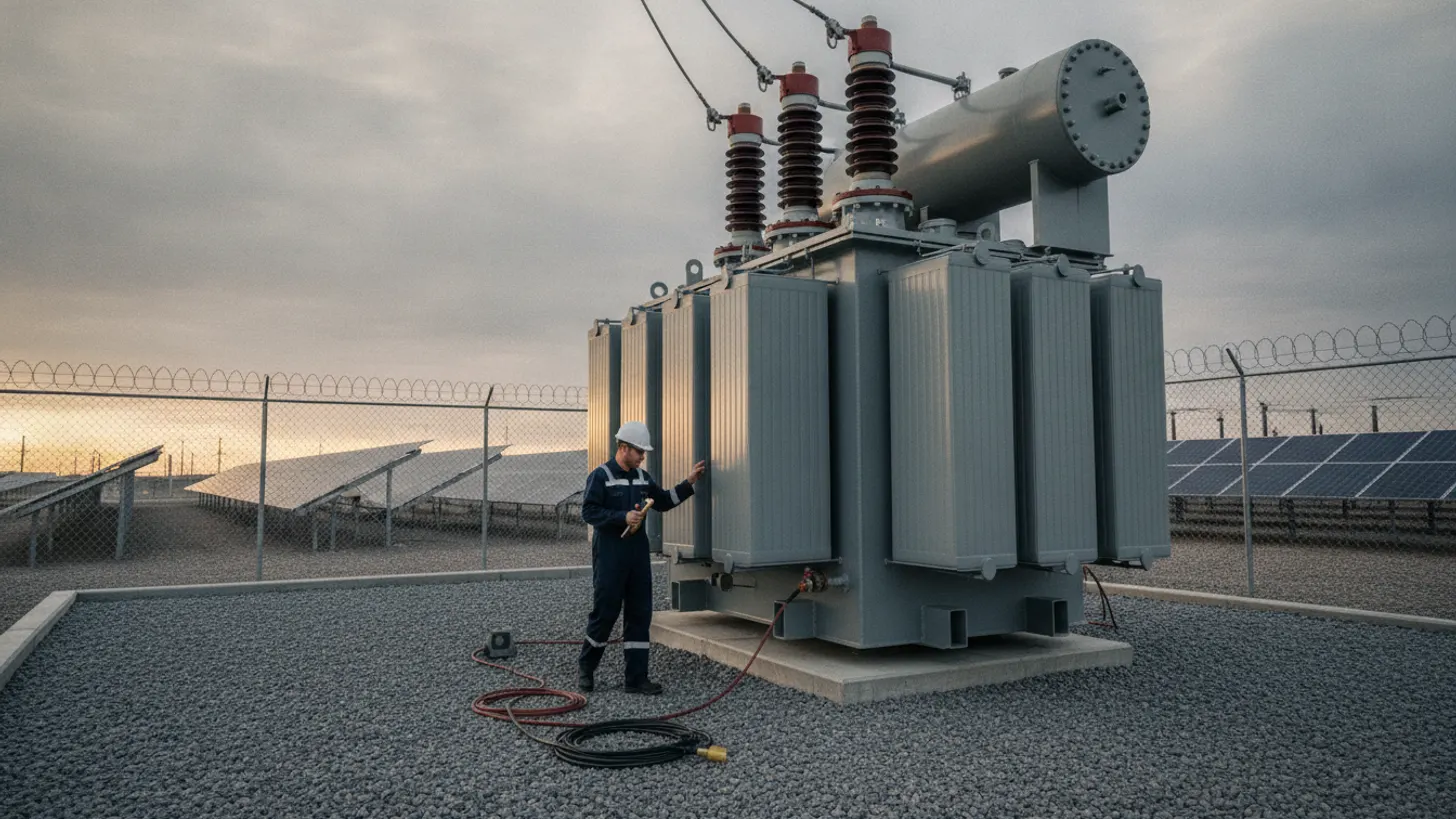
The Department of Energy has flagged long lead times for large power transformers as a standing grid constraint, which means a failed site acceptance test is rarely a two-week problem. That is why solar plant transformer commissioning deserves the same rigor as inverter or relay work: every electrical test named in IEEE C57.12.90 exists to catch a shipping, assembly, or dry-out defect while the unit is still the manufacturer's responsibility.
Which tests belong in a solar plant transformer commissioning plan?
A commissioning plan covers three populations: the main step-up unit at the point of interconnection, the medium-voltage units serving each inverter block, and the station service transformer feeding trackers and SCADA. All three take the same test families, scaled to voltage class, with the full sequence running several days per unit across two site visits.
The method side is settled. The IEEE standards catalog entry for C57.12.90 covers the test code for liquid-immersed distribution and power transformers, specifying how winding resistance, voltage ratio, polarity, phase relation, loss, impedance, and dielectric tests are performed. Field interpretation on an installed unit comes from the IEEE C57.152 guide for field testing of liquid-immersed transformers. One document tells the technician how to take the reading. The other tells your engineer what the reading means on a pad in a field in August.
Beyond the electrical set, a solar plant transformer commissioning plan has to prove the accessories, because a transformer the plant cannot see is a transformer the plant cannot protect. Winding temperature, top oil temperature, sudden pressure relay, gas accumulation, oil level, and tap position all need to land in the historian with correct scaling and alarm priority. Point-to-point checks on every alarm and trip contact belong in the same record set as the resistance data, and the work in our solar plant grounding and bonding field guide should close out first.
How should winding resistance, ratio, and impedance tests be performed?
Take winding resistance with a DC micro-ohmmeter once oil temperature is stable, record that temperature with every reading, and correct to a common reference before comparing anything. Ratio must land within 0.5% of nameplate on every tap, and impedance within 7.5% of the specified value. Polarity goes tap by tap, and impedance is measured per phase with the far winding shorted.
In solar plant transformer commissioning, winding resistance is the slowest test and the most often rushed. Inductive windings need settle time on each phase, and a reading taken before current stabilizes looks like a bad connection that is not there. Compare phase to phase on the same winding, compare the corrected set against the certified factory report, and repeat on every de-energized tap position rather than the service tap alone. A loose internal lead or a shipping-shifted connection shows here first.
Ratio testing is fast, which is why crews skip taps. Do not. IEEE C57.12.00, the general requirements standard for liquid-immersed transformers, holds measured ratio within 0.5% of nameplate on each tap, so every tap is a discrete pass or fail. Confirm the vector group, the nameplate code for how the primary and secondary windings connect and shift in phase, against the nameplate diagram, then confirm installed phase rotation against the collector system, because a correctly wired transformer on a rotated bus is still a fault waiting for first close.
Impedance, or leakage reactance, is the structural test. Measured per phase and as a three-phase equivalent, it is the most direct field evidence that the core and coil assembly survived the trip from the factory. IEEE C57.12.00 allows measured impedance within 7.5% of the specified value on a two-winding unit, but that is a design allowance, not your acceptance window. Your window is the factory number.
What insulation and oil tests reveal about transformer readiness
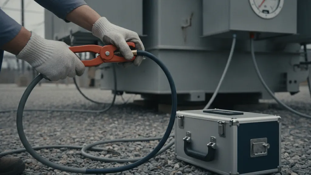
Insulation and oil tests answer a different question than the electrical set. Resistance, power factor, and excitation current describe whether the insulation system is dry and intact after shipping and field assembly. Oil analysis describes whether the fluid around it is fit to work.
Run insulation resistance winding to winding and winding to ground, hold long enough for a polarization index, the ratio between the ten-minute and one-minute insulation resistance readings that flags moisture before resistance alone does, rather than a spot reading, and correct for temperature before comparing to factory values. Dielectric power factor on windings and on each bushing catches moisture ingress that insulation resistance alone misses, and bushing power factor compared against the bushing nameplate value flags units damaged in transit. Lift the core ground link and confirm a single intentional core ground, since a second unintended path circulates current and heats the core for years without tripping anything.
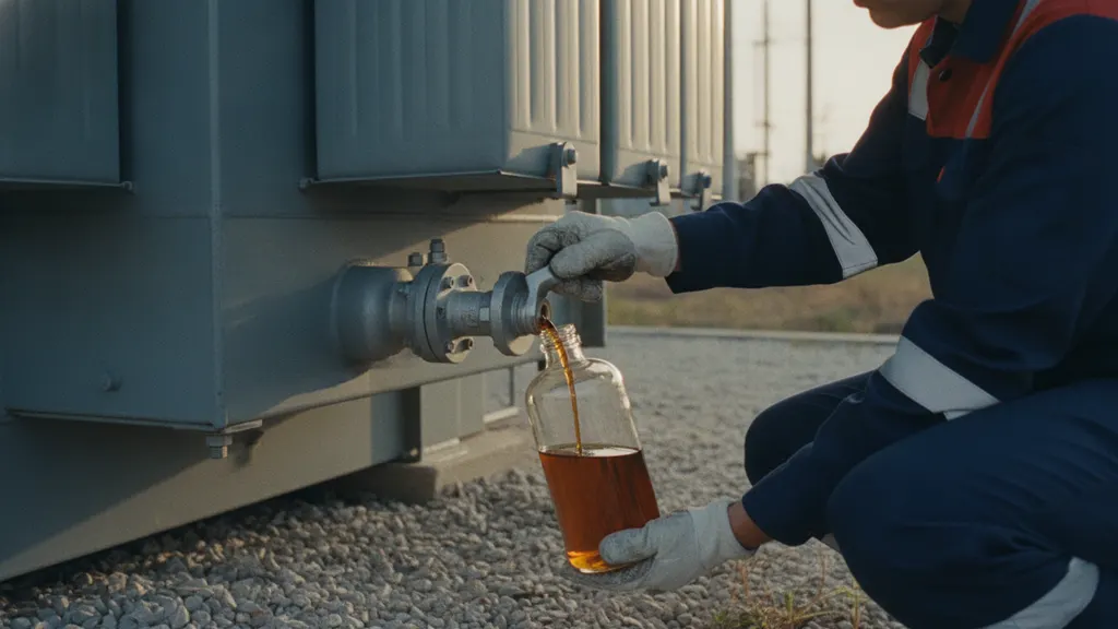
Oil is part of solar plant transformer commissioning, not a maintenance item deferred to the O&M team. After vacuum filling and the specified hold, sample for dielectric breakdown voltage, moisture, acidity, interfacial tension, color, and power factor, and judge the results against the acceptance values for new oil received in equipment in IEEE C57.106 rather than in-service limits. Pull a baseline dissolved gas analysis (DGA) sample before energization and a second after the first load period, since the pair is what makes later trending readable, as our transformer DGA field guide explains. Repeat diagnostics against a known baseline is also the reliability argument in EPRI research on transformer condition monitoring.
How should solar plant transformer commissioning results compare with factory data?
A field number means little alone. The certified factory test report is the baseline, and solar plant transformer commissioning results earn their value only when each reading is temperature corrected, logged with ambient conditions, and placed beside the factory figure for the same tap and phase, inside the same 0.5% ratio and 7.5% impedance bands set by IEEE C57.12.00.
Three habits separate a usable comparison from a pile of numbers. Record oil and winding temperature with every resistance and insulation reading, because an uncorrected comparison across a thirty degree spread manufactures deviations that do not exist. Record test set model, serial number, and calibration date, because a disputed result is only arguable when the instrument has traceable calibration behind it. Record who witnessed each test.
At a 120 MW inverter-block interconnection REIG commissioned near Lubbock, Texas in 2023, one medium-voltage unit came back from impedance testing 4.1% above its certified factory value on the A phase while B and C phases matched within 0.3%. Lead commissioning engineer Daniel Ruiz traced the gap to a shipping-shifted internal lead rather than a winding fault, confirmed it with a second measurement after the connection was re-torqued, and cleared the unit for energization once it matched the factory report within 0.4% on every phase. That single-phase signature, one leg off while the other two match, is exactly the pattern solar plant transformer commissioning is built to catch before energization.
Deviations then read as patterns. One phase of winding resistance off while the other two match points to a connection or tap contact. All three legs drifting together usually points at temperature correction or test leads. Ratio out of band on one tap points at the tap changer. Long replacement lead times, as Department of Energy assessments of large power transformer supply have described, are why this triage happens before energization rather than during the first outage.
Which solar plant transformer commissioning records should owners require from EPCs?
Require the records in the contract, not at turnover. Solar plant transformer commissioning records, six record types in all, are warranty evidence, protection evidence, and the baseline for the next decade of diagnostics, so an EPC that hands over a pass or fail summary without raw data has given you nothing to trend.
| Record | What it proves | When owners should hold it |
|---|---|---|
| Certified factory test report | Ratio, resistance, impedance, loss, and insulation values as built | Before the unit ships |
| Field electrical test report | Resistance, ratio, polarity, impedance, and insulation data with temperatures and instrument serials | Before energization |
| Oil processing and fluid test results | Vacuum level, hold time, and new-oil acceptance values | Before energization |
| Baseline dissolved gas analysis | Pre-energization and post-load gas reference points | Within the first load period |
| SCADA point-to-point verification sheet | Every alarm, trip, and analog mapped to its historian tag | At turnover |
| Nameplate, bushing, and accessory serial record | Asset identity for warranty claims and spares | At turnover |
Two records go missing reliably. The oil processing log, with vacuum level, hold time, and fill temperature, is the only evidence that dry-out happened to specification. The signed SCADA point list, mapping every transformer alarm and analog to its historian tag and alarm priority, is the only evidence that the monitoring you paid for exists. Protection records belong in the same package, including the relay and current transformer work covered in our transformer differential protection guide. For registered entities, several of these records also support obligations in the NERC reliability standards library.
Where solar plant transformer commissioning fits in the energization sequence
Sequence failures cost more than test failures. Solar plant transformer commissioning sits after grounding and medium-voltage cable work and before relay in-service checks, so a plan that runs transformer tests in parallel with trenching or cable pulling will pay to repeat them.
Prove the medium-voltage cable between the transformer and the collector system first, using the methods in our medium voltage cable testing field guide, because a cable fault found after energization puts the transformer through a through-fault it did not need. Prove the relay settings protecting the unit by injection before first close, as described in our secondary injection testing guide. Work on and around the equipment follows the OSHA 1910.269 standard for electric power generation, transmission, and distribution.
First energization is then deliberate. Energize at no load, hold the soak period in the specification, walk the unit for sound, oil level, and gauge behavior, confirm that every temperature and alarm point reads live in SCADA, and only then step load up through the inverter blocks. Reliability work from NREL on utility-scale PV plant performance keeps pointing at balance-of-system equipment rather than modules as the source of lost production hours.
Frequently asked questions
How long does solar plant transformer commissioning take before energization?
Plan several days per unit across two windows rather than a single visit. The electrical set, winding resistance on every tap, ratio, polarity and phase relation, impedance, insulation resistance and power factor, runs once the unit is set, filled, and held under vacuum per specification. Accessory and SCADA point-to-point checks, baseline oil sampling, and witness sign-off add a second window near energization. On a multi-block plant the inverter-block units repeat, so solar plant transformer commissioning scales with block count, not plant megawatts. Utility-scale schedules tracked by the Department of Energy Solar Energy Technologies Office keep compressing, which is where the pressure to shortcut comes from.
Can we skip field tests if the factory test report passed?
No. Factory routine tests prove the unit as it left the plant, which is why the IEC 60076 power transformer standard series and its IEEE counterparts treat routine and field testing as separate events. Between the test floor and the pad, the unit is shipped under a gas blanket or partly drained, trucked, lifted, re-assembled, and vacuum filled. Shipping damage, a shifted lead, a cracked bushing, or wet insulation all appear after the factory report was signed. Field tests compare against that report rather than replace it, and that comparison is your evidence if a warranty claim follows.
Who should witness transformer commissioning tests on a solar project?
Have the owner or the owner's engineer witness the readings that cannot be re-created later: ratio on all taps, impedance, insulation power factor, the core ground check, and the oil processing hold. Those readings become your ten-year baseline. Require the test set model, serial number, and current calibration certificate in the report, since a result you may have to argue in a warranty dispute has to rest on traceable instruments, the principle behind NIST guidance on measurement traceability. Witness points belong in the contract, not in an email the week of energization.
What should we do if a field reading does not match the factory value?
Stop and triage before energization. One phase off its factory value while the other two match usually means a connection, lead, or tap contact rather than a winding. All three drifting the same way usually means temperature correction or a test lead issue, so re-check your reference temperature first. Ratio off on a single tap points at the tap changer. Document the deviation, the retest, and the resolution in the same report. Resolving it while the unit sits inside the EPC scope is far cheaper than after turnover, which matters at the fleet scale tracked by SEIA, the Solar Energy Industries Association.
How often should transformer tests be repeated after the plant is online?
Treat commissioning as the first data point in a program. Oil sampling and dissolved gas analysis repeat on an annual or semi-annual interval depending on unit criticality, with winding resistance, power factor, and excitation current repeated at longer intervals or after a through-fault, a relay operation, or an alarm you cannot explain. Thermal and gas data should stream into SCADA so trends stay visible between site visits. Field work from NREL solar research on PV plant operations keeps finding balance-of-system equipment, not modules, behind lost production hours.
What safety rules apply while testing a solar substation transformer?
Treat the transformer as energized until your own crew has grounded it. Test voltages applied during insulation and ratio work are hazardous, the high side can be backfed from the collector system, and bushings hold charge after a dielectric test. Work under a documented lockout and tagout, verified absence of voltage, and temporary protective grounds, with approach distances and arc flash boundaries set by the hazard analysis. OSHA electrical safety standards for power generation and distribution work govern qualified-person requirements and the energized work rules that apply during final checks near a live substation.