
Solar plant grounding and bonding: IEEE 80 safety field guide
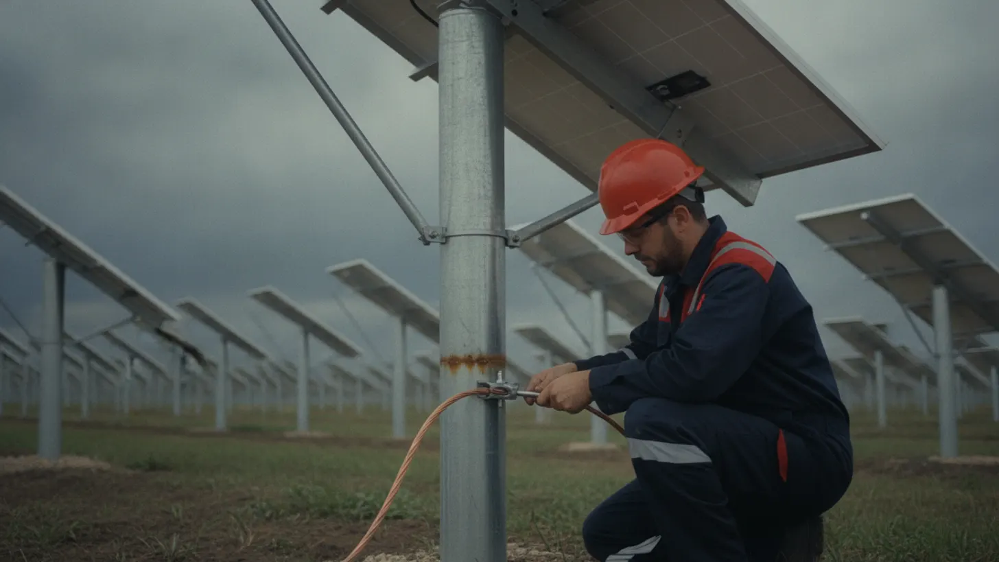
IEEE Std 80-2013 sets tolerable touch and step voltage limits that fall as fault clearing time rises. With a 3000 ohm-meter crushed rock surface layer, the 70 kg touch voltage criterion computes to roughly 1,930 volts at a 0.2 second clearing time and roughly 860 volts at 1.0 seconds. That single relationship drives most solar plant grounding and bonding decisions on a utility-scale site, from conductor sizing to how thick the surface layer needs to be.
How should solar plant grounding and bonding be designed for utility-scale sites?
Design starts with measured soil resistivity, the available ground fault current from the interconnection study, and the protection clearing time. Those three inputs set the grid geometry. Everything after that, conductor size, rod depth, mesh spacing, and surface layer thickness, is arithmetic against the tolerable voltage limits in IEEE Std 80-2013.
Soil resistivity comes first because every downstream number depends on it. A Wenner four-electrode traverse, run at several probe spacings along at least two orthogonal lines, produces an apparent resistivity curve that gets fitted to a two-layer model. IEEE Std 81, the guide to measuring earth resistivity and ground impedance, defines both the array geometry and the arithmetic. Sample in the season the site is driest, because a grid designed on spring readings can fall out of compliance in August. On a 200 MW project in Kern County, California, that REIG commissioned in 2019, the as-tested resistivity came in 40 percent higher than the geotechnical report had assumed, which pushed the surface layer spec from 4 inches to 6 inches of crushed rock before the grid passed its mesh voltage check.
The second input is ground fault current at the collector substation, with the decrement factor and the split between earth return and the overhead shield wire or cable shields. Those values live in the solar grid interconnection study, and the clearing times come from the relay settings you proved during secondary injection relay testing. A grid sized against a 0.5 second clearing time is no longer compliant if the backup scheme actually takes 1.2 seconds.
A utility-scale PV plant splits solar plant grounding and bonding into two separate design problems. The collector substation is a dense grid where ground potential rise, mesh voltage, and step voltage govern. The array field is a sprawling network where continuity, conductor sizing, and equipment bonding govern, and where pile foundations act as thousands of incidental electrodes that lower measured impedance but cannot be credited without proven continuity. The NREL solar energy research program publishes plant reliability work that keeps returning to the same theme: the field side fails on workmanship, not on math.
What does IEEE 80 require for touch and step voltage safety?
IEEE Std 80-2013 does not set a single voltage limit. It sets a tolerable body current for a given shock duration, then converts that to tolerable touch and step voltages using body weight criteria, foot contact resistance, and the resistivity of any surface layer. Longer clearing times mean lower allowable voltages.
The tolerable touch voltage for the 70 kg body criterion scales with the inverse square root of shock duration and rises with the resistivity of the surface layer. With a 3000 ohm-meter crushed rock layer and a derating factor near unity, the limit computes to roughly 1,930 volts at 0.2 seconds and roughly 860 volts at 1.0 seconds. The 50 kg criterion yields lower limits and is the conservative choice where a mixed workforce has access. Both formulations are published in IEEE Std 80-2013, the IEEE guide for safety in AC substation grounding.
Design verification then compares three computed quantities against those limits: ground potential rise, mesh voltage at the worst case corner cell, and step voltage across one meter at the grid perimeter. Ground potential rise (GPR) is the maximum voltage the grounding grid can reach relative to a remote point of earth during a fault, the single number that sets how far a hazard can reach beyond the fence line. GPR above the tolerable touch voltage is not automatically a failure, because the surface layer and the grid geometry can hold mesh voltage well below GPR. GPR does drive the transferred potential question for SCADA and control circuits, which is why isolation transformers and fiber links appear at the fence line.
Those three checks are the arithmetic backbone of solar plant grounding and bonding review, and they are the part a reviewer can audit line by line against the measured soil model.
How should solar plant grounding and bonding be tested in the field?
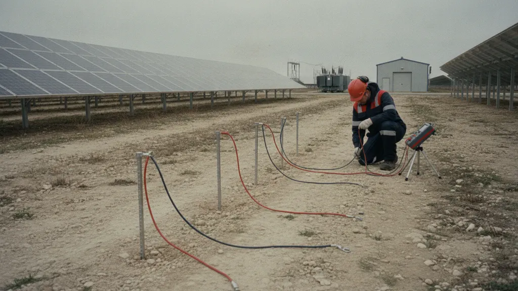
Testing proves two different things: the impedance of the grounding system to remote earth, and the continuity of every bond that is supposed to carry fault current. The first is an instrument and geometry problem; IEEE Std 81 alone lists four accepted measurement methods for it. The second is a walkdown problem, and it is where most as-built packages fall apart.
| Method | What it measures | Reference | Typical use |
|---|---|---|---|
| Wenner four-electrode array | Apparent earth resistivity against depth | IEEE Std 81 | Pre-design soil model for the substation grid |
| Fall-of-potential, 61.8 percent rule | Ground impedance of the electrode system | IEEE Std 81 | Small or electrically isolated electrodes |
| Slope or intersecting-curves method | Ground impedance of large grids | IEEE Std 81 | Grids where a really remote probe is impractical |
| Clamp-on or induced frequency | Rod and downlead loop resistance | IEEE Std 81 | Tracker row and combiner skid spot checks |
| Low-resistance ohmmeter | Bond and continuity resistance | IEEE Std 81 practice | Module frames, tracker bearings, skid bonds |
| Injected-current step and touch survey | Measured surface voltage gradients | IEEE Std 80 and 81 | Energized substation and fence line checks |
Fall-of-potential with the 61.8 percent rule assumes a compact electrode and a remote current probe, which rarely fits a solar collector grid tied to buried counterpoise running out into the array. A probe spacing shorter than four to five times the maximum grid dimension will underestimate impedance, which is the single most common error REIG finds when reviewing third-party solar plant grounding and bonding test reports; the fix is to rerun the slope method rather than trust a short fall-of-potential curve. The slope method and the intersecting-curves method exist for that case. Clamp-on readings help on single rods and downleads but report a loop rather than an impedance to earth, so they belong in spot checks rather than acceptance records. Keep instrument calibration traceable: most clamp-on and ground testers need factory recalibration every 12 months to stay within the manufacturer's stated accuracy, and NIST, the US national measurement institute maintains the traceability chain that makes a resistance reading defensible years later.
Bond resistance is the other half of the job. A low-resistance ohmmeter at the tracker bearing, module frame clip, inverter skid, and combiner enclosure catches what a grid impedance test never will, and tracker commissioning walkdowns are the right place to capture those readings. PV reliability research from EPRI, the Electric Power Research Institute, points the same direction: connections, not conductors, drive most findings. Photograph every below-grade connection before backfill, because afterward the only evidence is a number on a form.
Which solar plant grounding and bonding failures create personnel hazards?
Solar plant grounding and bonding hazards are almost never a missing ground grid. REIG's post-energization walkdowns typically find bond problems on 2 to 4 percent of tracker rows, not in the grid conductor. It is a bond that was never made, corroded, or removed during a repair and never restored, and each one creates a difference of potential a worker can bridge with two hands or two feet.
Recurring findings on utility-scale sites include tracker torque tube bonds that rely on a bearing or a fastener instead of a listed bonding jumper, so row continuity drops as the bearing wears; copper to galvanized steel connections made without a bimetallic transition, which corrode until the joint reads open; mechanical connectors used below grade where an exothermic weld was specified; inverter and transformer skid bonds landed on painted steel instead of a prepared surface; equipment grounding conductors in combiner circuits sized against the wrong fault current; and perimeter fence sections left unbonded or bonded in a way that drags substation potential to a reachable surface. I found this pattern firsthand on a 150 MW tracker project outside Abilene, Texas, in 2021: a post-energization walkdown turned up forty-one torque tube bonds reading open circuit because the installation crew had trusted a zinc-plated lock washer instead of the specified bonding jumper. None of those forty-one rows would have shown up in a substation ground impedance test, which is why the array-field walkdown matters as much as the grid calculation.
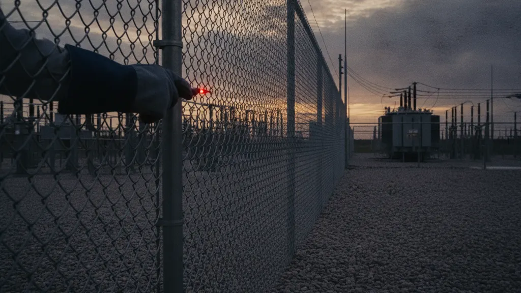
Two of those matter more than the rest because they scale. Fence bonding puts substation ground potential rise where the public can touch it, and tracker row continuity breaks silently across hundreds of rows. The employer duty to protect workers from shock and hazardous differences of potential, described in the OSHA electrical safety standards overview, applies to both. Lightning current adds a second path problem that IEC 62305 lightning protection design treats separately, and the IEC, publisher of the 62305 series, keeps surge and power frequency requirements distinct. A solar plant grounding and bonding package has to satisfy both.
What documentation should owners retain after solar plant grounding and bonding verification?
Retain enough that a stranger can reproduce your conclusion in 5 years: the soil model, the computed limits, the measured values, the instrument list, an exception log, and the test dates, 6 records in all. A pass or fail summary with no data behind it is not a verification record.
The turnover package should hold an as-built grid drawing showing rod and conductor locations with splice types, the raw resistivity traverse data with probe spacings and test dates, the design calculation naming the standard edition and every input, test records listing instrument model, serial number, calibration date, and method, pre-backfill photographs keyed to drawing locations, a bond resistance log indexed by asset tag, and a punch list with closure evidence attached.
Those records also feed worker protection programs. Energized work boundaries and grounding assumptions in a lockout tagout program only hold if the bonds sit where the drawing says. OSHA 29 CFR 1910.269 places the duty to protect employees from hazardous differences of potential on the employer, which makes solar plant grounding and bonding documentation an operating record rather than a closeout formality. Owners tracking long-term plant performance through programs such as the DOE Solar Energy Technologies Office treat it the same way. OSHA's rule does not set a single retention period for grounding test data, but the plant's NERC compliance program usually does, often 5 years for registered facilities and longer for any record tied to an open corrective action. REIG's practice is to retain the full soil model and every test report for the life of the plant, roughly 30 to 35 years, because a single retest years later is cheaper than re-deriving a design from scratch.
Frequently asked questions
How often should a solar plant ground grid be retested?
No standard fixes a single interval. The defensible approach ties retesting to change rather than the calendar: new piles, new trenches, a replaced transformer, a substation modification, or a fence line that was cut and repaired. Between those events, bond resistance spot checks in the array field catch slow corrosion. The measurement methods and the recording conditions that make one year of readings comparable to the next are given in IEEE Std 81, available from IEEE standards. Treat retesting of solar plant grounding and bonding as a condition-triggered task with a periodic floor.
Can tracker piles count as the grounding electrode system?
Driven piles do lower measured impedance, sometimes sharply, since a utility-scale site has thousands of them in soil contact. Crediting them in a design is different. The pile must sit below the galvanizing damage zone, the pile-to-structure connection must be a listed bonding path rather than a bolted joint relying on paint removal, and continuity must be measured, not assumed. Plant reliability work published through NREL keeps finding structural bonding paths that degrade mechanically. Design the electrode system to stand without the piles, then let the piles help.
What is the difference between grounding and bonding on a PV plant?
Grounding connects the system to earth so that fault current has a return path and the plant reference stays near earth potential. Bonding ties conductive parts to each other so that two surfaces a person can touch at the same time stay at the same potential. Grounding handles the fault. Bonding handles the person. A plant can show excellent grid impedance and still injure someone because a tracker row lost continuity. Technical guidance collected by the US Department of Energy uses the same split, and so does every acceptance test plan worth signing.
Why does my measured ground resistance differ from the design value?
Four usual reasons. Soil moisture at test time differs from the design condition, so an August reading beats a March one. The test geometry was too short for the grid size, so the curve never flattened. Buried metal, cable shields, water lines, or nearby structures created parallel paths the model missed. Or the instrument was out of calibration, which is why traceability through NIST calibration services belongs in the test record. Resolve the difference on paper before accepting the grid, since an unexplained gap usually means the soil model is wrong, not the grid.
Do I really need a crushed rock surface layer in the collector substation?
It is the cheapest safety margin available. A high resistivity surface layer raises the tolerable touch and step voltage limits by adding resistance in series with the body, often turning a marginal design into a compliant one without adding copper. The derating factor for layer thickness and the soil beneath it is defined in the IEEE Std 80 calculation sequence published by IEEE. The layer only works if maintained: vegetation, tracked-in mud, and thin spots at gate approaches all defeat it. Inspect it the way you inspect a fence.
Who is responsible for solar plant grounding and bonding records after commercial operation?
The owner, in practice. The EPC produces the as-builts and test reports, but the obligation to show that the plant is safe to work on sits with whoever employs or controls the people working on it. That means solar plant grounding and bonding records belong in the owner document control system alongside relay settings and one-lines, not in a closed contractor project folder. Registered entities also face documentation expectations from their regional reliability program under NERC, the North American Electric Reliability Corporation. Transfer the records at turnover and keep them under revision control.