
Pyranometer Installation: Mounting, Leveling, and Shading Rules for Utility-Scale PV
Pyranometer Installation: Mounting, Leveling, and Shading Rules for Utility-Scale PV
Irradiance data is one of the fastest ways to lose (or earn) trust in a utility-scale solar SCADA + DAS stack. When a pyranometer is mounted poorly, slightly out of level, or shaded by something “minor,” the sensor can still report plausible numbers—while quietly driving wrong PR, wrong expected power, and avoidable disputes during commissioning and after COD.
This guide is written for utility-scale owners/operators, developers, EPCs, commissioning leads, SCADA/DAS engineers, and O&M teams who need pyranometer data that is defensible from day one. We’ll cover practical mounting, leveling, and shading rules, plus a commissioning checklist you can use to validate the signal end-to-end.
What a pyranometer is (and why installation quality matters)
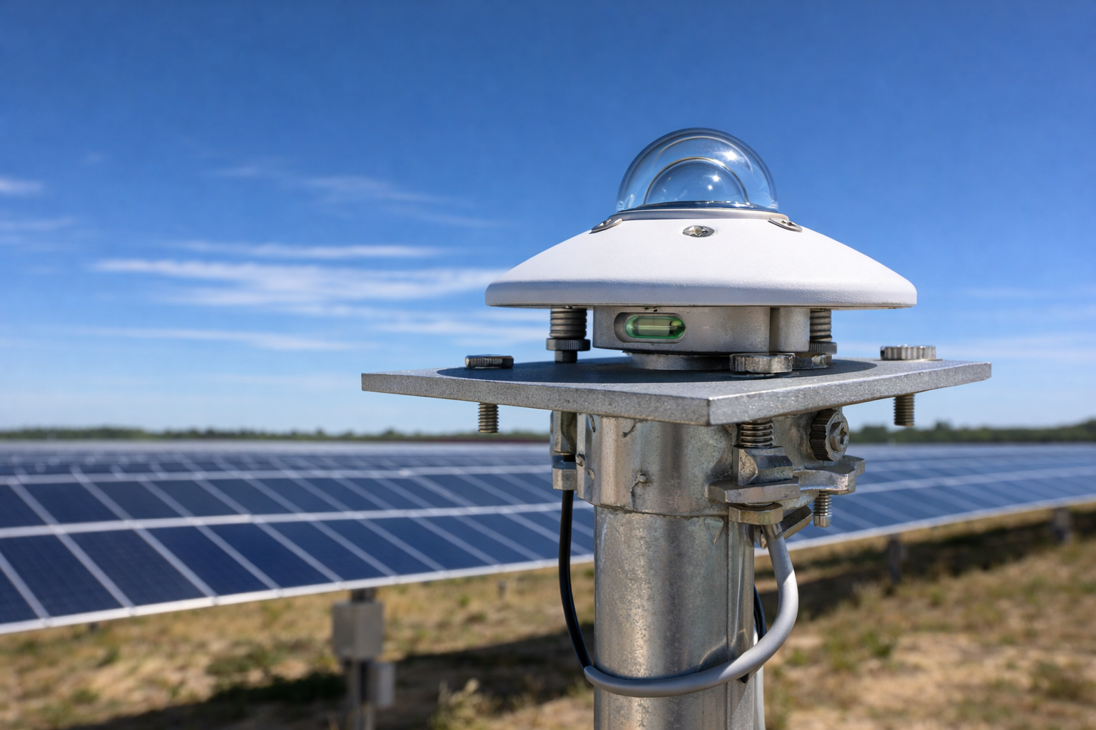
A pyranometer measures solar irradiance (solar radiation power per unit area), typically reported in W/m². In PV plants it’s commonly used to measure:
- GHI (Global Horizontal Irradiance): irradiance on a horizontal plane (often used for meteorological context and some performance models).
- POA (Plane of Array) irradiance: irradiance in the plane of the modules (commonly used for expected power, PR calculations, and acceptance/performance testing).
In practice, installation quality matters because pyranometers have a wide field of view. Small installation issues (tilt error, nearby reflections, intermittent shade) can create systematic bias that looks like “real weather”—and can be very hard to diagnose later.
Mounting location: pick the site like you’re defending a PR calculation
If you want irradiance data that holds up in performance testing and monthly reporting, treat the location decision as a design deliverable, not a field preference.
Rule 1: keep the field of view clear (especially near the horizon)
Pyranometers “see” much of the sky dome. Obstructions near the sensor (poles, rails, lightning masts, tracker torque tubes, weather station structures) can cause morning/evening shading and biased daily totals. Guidance for pyranometer use in solar testing emphasizes controlling the sensor’s field of view and minimizing obstructions that compromise representative measurement. (IEA SHC Task 9 guide)
Rule 2: avoid reflective surfaces near the dome
Many pyranometer manuals caution against proximity to light-colored or reflective objects because they can reflect extra sunlight onto the sensor and inflate readings. Kipp & Zonen’s guidance, for example, notes that the sensor should be distant from light-colored walls or objects likely to reflect sunlight onto it. (Kipp & Zonen CM22 manual)
Common “gotchas” on utility-scale sites:
- galvanized poles, unpainted conduit, bright equipment cabinets
- white fiberglass enclosures or sunshields mounted too close
- snow/standing water near the sensor (seasonal reflection)
Rule 3: mount to a stable structure that won’t settle or twist
A pyranometer that is perfectly level on day 1 can drift out of level after a few storms if the mast, crossarm, or bracket flexes. Choose a rigid mount with locking hardware and easy access for re-leveling during O&M.
Rule 4: keep it maintainable (cleaning and inspections are part of accuracy)
Dirt, pollen, bird droppings, and condensation can degrade readings. Put the sensor somewhere techs can access safely for cleaning and bubble-level checks without “special” equipment or risky climbs.
Mounting hardware: what “good” looks like in the field
Mounting details vary by vendor, but reputable manufacturers converge on a few core ideas: rigid mounting, thermal considerations, and a repeatable leveling method.
Use the right plate/bracket and don’t create a heat problem
Some OEM guidance recommends using a non-conducting mounting plate to thermally isolate the sensor from the fixture and reduce temperature-driven offsets. (Vaisala installation guidance)
On PV sites, this matters because mounts can heat unevenly (sun-exposed steel crossarms, enclosures, tracker structures). Even if the sensor is “working,” thermal effects can add noise or bias.
Route cable and connector orientation deliberately
Orientation guidance differs by product, but several manuals include practical advice to avoid creating heat or water ingress issues at the connector. For example, Vaisala notes cable/connector orientation to reduce heating of electrical connections when the sensor is mounted horizontally. (Vaisala installation guidance)
Field best practices:
- Use drip loops and avoid upward-facing cable entries.
- Strain-relief the cable so vibration doesn’t torque the sensor.
- Keep signal cable routing separated from high-noise conductors where practical.
Leveling: the “small” step that creates big performance-test risk
Leveling is not cosmetic. If the sensing surface is tilted, the irradiance measurement is biased, especially at low solar elevations. Some OEM documentation specifies tight leveling tolerances; for example, Vaisala references a ±0.05° leveling tolerance and discusses the resulting measurement variation at low sun angles. (Vaisala installation guidance)
How to level a pyranometer (repeatable field method)
Most pyranometers include a bubble level and leveling screws. A typical process (also reflected in NOAA-hosted instrument manual instructions) is: mount the base securely, adjust leveling screws until the bubble indicates level, then lock hardware so it can’t drift. (NOAA-hosted pyranometer manual)
- Secure the mount (don’t level on a loose bracket).
- Adjust leveling screws incrementally; re-check after each adjustment.
- Rotate your viewpoint around the bubble (parallax can trick you).
- Tighten/lock hardware and re-check the bubble after tightening.
- Record: date, installer, and “as-left” bubble position (photo is useful for turnover).
Commissioning reality: leveling should be treated like a QC point
Leveling is easy to do “once,” but it’s also easy to lose due to settling, vibration, and rework on the mast. Treat leveling as a commissioning deliverable: checked, documented, and re-checked before performance testing and COD.
Orientation: when it matters (and when it doesn’t)
Many pyranometers are designed to measure hemispherical irradiance and do not require a specific azimuth orientation for basic measurement. However, accessories (shading rings, ventilators/heaters, cable exit direction, sun tracker mounts) can introduce orientation requirements. Always follow the instrument manual for your exact model.
If you’re using a shading device or mount that has a “preferred” direction, follow the manufacturer guidance and document it in your as-built package. Commissioning teams should treat orientation as part of “installed per spec,” not an aesthetic detail.
Shading and obstruction rules: what to avoid (and what to document)
For utility-scale PV, the most costly shading errors are the ones that only show up under certain sun positions—because they create day-to-day variability in PR and expected power.
Hard “no” list (typical PV site pitfalls)
- Mounting too close to a pole/mast that shades the dome at low sun angles.
- Mounting near light-colored cabinets or walls that can reflect sunlight onto the sensor. (Kipp & Zonen CM22 manual)
- Mounting under or adjacent to a tracker row edge where backtracking/stow changes the shading pattern.
- Mounting where periodic maintenance activities block the sensor (parked trucks, staged materials).
When shading is unavoidable: make the risk explicit
Sometimes site constraints force a compromise. If you can’t achieve a clean horizon, do two things:
- Document the obstruction geometry (photos plus notes on time-of-day impact).
- Put data-quality flags in the DAS (for example, an “irradiance shaded” indicator during known periods) so the operations and analytics teams aren’t forced to guess later.
POA vs GHI installs: decision criteria for utility-scale PV
Many sites deploy both POA and GHI. The installation rules overlap, but the “representativeness” question is different.
| Measurement | Primary use in PV | Install focus | Common mistake |
|---|---|---|---|
| POA irradiance | Expected power, PR, acceptance testing | Match array plane; avoid row-edge shading; stable tilt/azimuth | Mounting where tracker geometry shades the sensor part of the day |
| GHI | Meteorological reference, model inputs | True horizontal leveling; clear sky view; avoid reflections | “Close enough” leveling or nearby reflective hardware |
Commissioning checklist: prove the irradiance channel end-to-end
A pyranometer can be perfectly installed and still be “wrong” in your data stack due to wiring, scaling, units, or timestamp issues. For utility-scale commissioning, treat the irradiance point like a Tier 1 data-quality signal: verify it from the sensor all the way into the historian and dashboards.
Mechanical & environmental checks
- Sensor is rigidly mounted; all hardware tightened and locked.
- Bubble level centered after final tightening (photo documented). (NOAA-hosted pyranometer manual)
- Clear field of view: no obvious shading at sunrise/sunset paths.
- No nearby reflective surfaces (walls, enclosures, bright metal). (Kipp & Zonen CM22 manual)
- Cable routing includes drip loop and strain relief.
Electrical & data checks (SCADA/DAS)
- Confirm the correct sensor type and calibration factor are used in the logger/RTU input channel (per OEM documentation).
- Verify units displayed in SCADA/HMI and stored in historian are W/m² (and consistent across layers).
- Confirm scaling is applied in one place (no double scaling). If using a transmitter or analog input scaling, document the formula.
- Validate time alignment: timestamps are correct and consistent with plant time source.
- Verify historian sample interval/averaging matches reporting needs (and your plant’s data standard).
Operational sanity checks (quick tests that catch real problems)
- Nighttime check: irradiance should be near zero at night; sustained offset suggests wiring/scaling/thermal issues.
- Midday reasonableness: on clear days, readings should be consistent with expectations for season and location (you don’t need perfect modeling—just “not obviously wrong”).
- Step-change check: passing clouds should create smooth ramps, not “stair steps” or clipped values (which can indicate signal conditioning issues).
O&M: keep the pyranometer trustworthy after COD
Installation is the beginning. A durable operations plan includes periodic checks that prevent slow drift from becoming a reporting fight.
- Cleaning: clean dome per OEM recommendations and site conditions (pollen/soiling seasonality matters).
- Re-leveling: bubble-level check on a defined cadence and after major weather events or nearby construction.
- Inspection: verify mount rigidity, corrosion, cable strain relief, and connector condition.
- Data QC: track simple health indicators (nighttime baseline, clipping at max range, missing samples) in the DAS.
Where REIG fits: commissioning-ready irradiance data in a full SCADA + DAS stack
For utility-scale PV, pyranometer installation is not just a mechanical task—it’s part of making plant performance data defensible. REIG supports end-to-end SCADA + DAS integration (including commissioning and signal verification) so key inputs like irradiance arrive correctly in the historian and dashboards, with clear units, scaling, and documentation that survives handoff.
Conclusion: install it like you’ll have to prove it later
Pyranometer data drives decisions: expected power, PR, curtailment narratives, and performance testing outcomes. If you mount rigidly, level precisely, control shading/reflections, and verify the signal end-to-end during commissioning, you dramatically reduce “mystery” performance questions later.
Done right, a pyranometer becomes one of the most trusted sensors on site—because everyone knows the installation, data path, and QC are solid.
Further reading
- Solar SCADA + DAS integration services
- Commissioning and end-to-end signal validation
- DAS tagging: units, scaling, and QC
- Post-COD SCADA and DAS support
FAQ
How level does a pyranometer need to be?
Follow the manufacturer’s requirement for your model, but treat leveling as a precision step—not “close enough.” Some OEM guidance specifies tight tolerances (for example, Vaisala references a ±0.05° leveling tolerance) because small tilt errors can bias readings, especially at low sun angles. In commissioning, document the final bubble level position and re-check it after tightening hardware.
What’s the biggest installation mistake that causes “plausible but wrong” irradiance data?
Intermittent shading or reflections. A pyranometer can read smoothly all day while being biased upward by nearby reflective surfaces or biased downward during morning/evening shade from poles and structures. Those errors often show up later as PR disagreements, expected power issues, or unexplained seasonal variance.
Where should we mount the pyranometer on a utility-scale solar site?
Mount it where it has a clear, representative field of view and where it can be maintained safely. Avoid mounting near bright/reflective objects, poles, and tracker geometry that changes shading patterns (stow/backtracking). If constraints force a compromise, document it and consider adding data-quality flags for known shading windows.
Do pyranometers need to be pointed south (or north)?
Not always—many pyranometers measure hemispherical irradiance and don’t require a specific azimuth orientation for basic measurement. However, mounts, shading devices, ventilators/heaters, and cable/connector guidance can introduce a preferred orientation depending on the manufacturer and configuration. The practical rule is to follow the exact instrument manual and document the as-built orientation in turnover.
How do we commission a pyranometer signal so the SCADA screen and historian agree?
Verify it end-to-end: correct sensor type and calibration factor in the logger/RTU, correct scaling applied in only one layer, W/m² units consistent across SCADA/HMI and historian, and correct timestamps/time sync. Then run simple sanity checks (near-zero at night, reasonable midday values on clear days, smooth response to passing clouds). Finally, capture evidence (screenshots/photos) as part of commissioning documentation.
Further reading
References
- IEA SHC Task 9: Using Pyranometers in Tests of Solar Energy Converters (PDF)
- Vaisala Product Documentation: Installing pyranometers (AWS810)
- Kipp & Zonen: CM 22 Precision Pyranometer Manual (PDF)
- NOAA Physical Sciences Laboratory: Pyranometer Manual (PDF)
- Campbell Scientific: LI200X Pyranometer Manual (PDF)
Next step
If you’re commissioning a new site or troubleshooting PR/expected-power disagreements tied to irradiance, REIG can help you validate pyranometer signals end-to-end (sensor → logger/RTU → network → SCADA/HMI → historian) and deliver clean documentation that keeps plant data trustworthy from day one. Reach out to scope a commissioning-ready SCADA + DAS plan that reduces rework and eliminates “mystery” data gaps.


