
Solar plant arc flash analysis: OSHA and IEEE 1584 field guide
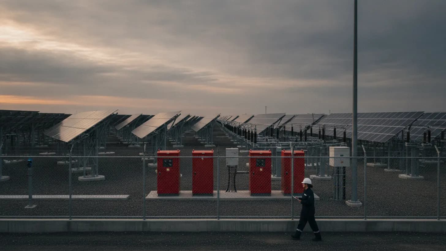
OSHA 1910.269 requires arc-rated protection wherever estimated incident energy exceeds 2.0 cal/cm2, and IEEE 1584-2018 draws the arc flash boundary where incident energy reaches 1.2 cal/cm2. Those two numbers decide how a technician dresses to rack a medium-voltage breaker. A solar plant arc flash analysis converts plant-specific fault current into those thresholds, and on PV sites the inverter contribution is the input most studies get wrong.
When does a utility-scale plant need a solar plant arc flash analysis?
Any time a worker can reach inside the arc flash boundary of equipment energized above 50 volts, the employer owes a documented hazard assessment. On a utility-scale PV site that covers the collector substation, the medium-voltage ring, inverter skids, DC combiner enclosures, and the auxiliary panels feeding trackers, met stations and SCADA cabinets.
OSHA 1910.132, the hazard assessment and PPE selection rule, obliges the employer to assess the workplace and select protection matched to what the assessment finds, while OSHA 1910.335 on safeguards for personnel protection requires protective equipment for work near exposed energized parts. Neither rule names a calculation method. That gap is what IEEE 1584 fills: it supplies the arithmetic that turns a short-circuit model into incident energy in cal/cm2 at a stated working distance.
In practice the trigger is commissioning. The study belongs in the package before the first energization sequence, because the commissioning crew is the most exposed group on site: breakers are racked in and out repeatedly as punch-list items get cleared, relays are still being proven with secondary injection relay testing, and interlocks have not been validated against the as-built wiring. That sequence puts technicians closest to live parts at the exact moment the protection scheme is least trustworthy, which is the opposite of how most schedules treat the paperwork. Waiting until substantial completion to issue a solar plant arc flash analysis gets the labels right for steady-state operation but leaves the highest-risk phase of the whole project, energization and commissioning, running on guesswork instead of a calculated boundary.
How to model inverters, transformers and BESS in a solar plant arc flash analysis
Model the plant as two fault-current regimes. Upstream of the point of interconnection the utility source behaves like a stiff conventional system with a defined short-circuit MVA. Downstream, inverters and battery enclosures are current-limited power electronic sources whose contribution is set by firmware limits and ride-through logic rather than machine reactance.
That difference matters. A synchronous generator contributes a decaying subtransient current many times its rating, while a PV inverter holds near its own current limit for the duration of the sag and then either rides through or stops injecting. NERC guidance on inverter-based resource performance and EPRI research on inverter-based resource short-circuit behavior both describe this, and the consequence is that a classical generator model misstates plant contribution depending on which clearing time the relay actually uses.
Ask each inverter and PCS vendor for four data points: the steady-state current limit during a bolted fault, how that limit varies with retained voltage, the time before internal protection removes the unit, and the ride-through profile in the plant's as-set configuration. Those same settings drive islanding detection, covered separately in our guide to inverter anti-islanding protection under IEEE 1547.
Transformers set the rest of the arithmetic. Low-impedance inverter-skid pad-mounts raise available fault current on their secondary, and the collector substation transformer defines what the medium-voltage ring sees. Grounding arrangement changes the single-phase picture, which ties back to ground grid design under IEEE 80.
Battery systems are a different problem again. A DC bus offers very high available current with no natural current zero, so an arc that forms does not self-extinguish the way an AC arc does at the next zero crossing, and it can sustain until something upstream interrupts it or the arc path burns open on its own. IEEE 1584-2018 does not cover DC arcs: its test basis is three-phase AC at 50 or 60 Hz, and the physics of sustained DC arcing simply are not in that data set. DC incident energy needs a separate method, and enclosure arrangement interacts with NFPA 855 fire safety layout for solar BESS. Running AC empirical equations against a battery string anyway, inside a solar plant arc flash analysis that never flags the substitution, hands the field a number that looks precise and means nothing.
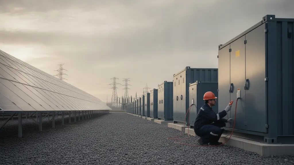
What IEEE 1584-2018 contributes to incident energy calculations
IEEE 1584-2018 replaced the 2002 empirical model with one derived from a much larger test program. It adds electrode configuration, an enclosure size correction, and a defined validity envelope, and it requires engineers to check two arcing current cases rather than one.
Five electrode configurations are defined: VCB, VCBB, HCB, VOA and HOA. Vertical conductors in a box with an insulating barrier direct more energy toward the worker than open-air vertical electrodes, so picking the wrong configuration moves the answer by a wide margin. The IEEE Standards Association catalog entry for IEEE 1584-2018 is the authority on which configuration belongs to which equipment class.
The validity envelope is the part most often missed on solar sites. The model covers 208 V to 15 kV, bolted fault current from 500 A to 106 kA, and electrode gaps from 6.35 mm to 254 mm. A 34.5 kV collector bus sits outside that range, so incident energy there is handled by other means, typically the open-air arc approach referenced in NFPA 70E informative annexes.
The standard also requires a second calculation at 85 percent of the predicted arcing current, because lower current can mean slower relay operation and more delivered energy. On a plant where inverter contribution is modest and the relay sits on a time-overcurrent curve, that 85 percent run often produces the governing number.
Typical gaps and working distances tabulated in IEEE 1584 give a defensible starting point for equipment classes on a PV site:
| Equipment class | Typical electrode configuration | Typical gap (mm) | Typical working distance (mm) |
|---|---|---|---|
| 15 kV switchgear | VCB or VCBB | 152 | 910 |
| 5 kV switchgear | VCB or VCBB | 104 | 910 |
| Low-voltage switchgear | VCBB | 32 | 610 |
| LV MCC and panelboards | VCBB | 25 | 455 |
| Cable junction box | VCB | 13 | 455 |
Record which configuration, gap and working distance were used for every bus. A reviewer cannot reproduce a result without them, and an unreproducible study is not a defensible one.
Turning solar plant arc flash analysis results into boundaries, labels and PPE
Three outputs leave the study and reach the field: the arc flash boundary where incident energy falls to 1.2 cal/cm2, the incident energy at the stated working distance, and the arc rating the clothing system has to meet. Labels carry those numbers to the technician standing at the door.
OSHA 1910.269(l)(8), the incident energy and arc-rated clothing rule, requires the employer to estimate incident energy for exposed work and to provide arc-rated protection where that estimate exceeds 2.0 cal/cm2. NFPA 70E 130.5(H) sets label content: nominal system voltage, arc flash boundary, and either incident energy with its working distance or the required PPE category. Mixing both label styles across one plant is how crews end up guessing.
Arc ratings are not a smooth scale. Category minimums step from 4 to 8 to 25 to 40 cal/cm2, so a bus calculated at 9 cal/cm2 and a bus calculated at 24 cal/cm2 land in the same clothing class even though one is almost three times hotter than the other, and a worker reading only the category number has no way to tell which side of that gap they are standing on. Reporting incident energy to two decimal places looks rigorous on paper, and it is the correct way to document the calculation, but a solar plant arc flash analysis report that stops there and never states the resulting PPE category has handed the crew a number they cannot act on without doing the lookup themselves in the field, which is exactly the moment nobody has the table in hand.
Label equipment the way a crew moves through it. Inverter skid, auxiliary panel and string combiner box fusing under NEC 690 decisions all change the number printed, and a label that disagrees with the as-built protection setting is worse than no label.
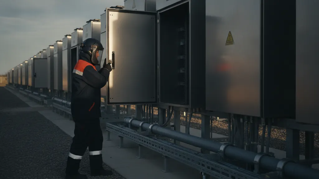
Field data and maintenance changes that force a solar plant arc flash analysis update
Treat the study as a living document tied to the protection settings file. Any change that moves available fault current, clearing time or equipment geometry invalidates the affected buses, and most plants accumulate several such changes within the first two operating years.
The usual triggers: a relay setting change, an inverter or transformer replacement with different impedance, a storage addition, a utility notice of changed source impedance at the point of interconnection, or a switch to maintenance-mode setting groups. Relay test records and as-built single-line drawings are the field data that keep the model honest, and test instrument calibration traceable to NIST measurement and calibration standards is what makes those records defensible.
Field evidence counts as much as paperwork. Thermography findings, loose connection reports and breaker timing results tell you whether modeled clearing times still hold. NREL utility-scale PV research and the DOE Solar Energy Technologies Office both publish material on how component behavior drifts across a plant's life, and clearing time drift is the variable a solar plant arc flash analysis is most sensitive to.
NFPA 70E 130.5 sets a review interval not exceeding five years. Treat that as a ceiling rather than a plan. A plant that re-dates labels every five years while changing relay settings every spring is documenting the wrong thing.
Frequently asked questions about solar plant arc flash analysis
Do I need an arc flash study for a solar farm if the utility already did one?
Yes. The utility study covers utility equipment and stops at the point of interconnection. Everything inside the fence, including the collector system, inverter skids, auxiliary distribution and the DC side, is the plant owner's exposure, and the employer owes the assessment under the OSHA electrical safety requirements. The utility model is still useful input because you need its source impedance and clearing times. What it cannot tell you is the incident energy at a 480 V auxiliary panel inside an inverter skid, which is exactly what a solar plant arc flash analysis produces.
Does IEEE 1584-2018 cover the DC side of a PV plant?
No. The 2018 model is built on three-phase AC testing at 50 and 60 Hz, as the scope published by IEEE states, so PV DC circuits fall outside it. DC arc flash is handled with separate methods referenced in NFPA 70E informative annexes, which work from arc power and arc resistance rather than the AC empirical equations. Your DC combiner and battery string calculations need a documented alternative method, stated clearly in the report so a reviewer can see the AC equations were not misapplied.
How much fault current does a PV inverter actually contribute?
Close to its own current limit, and only for as long as its controls allow. Unlike a synchronous machine, an inverter does not produce a large decaying subtransient current, so the contribution is bounded by firmware rather than machine reactance. Research on inverter-based resources published through NREL describes this behavior. The number you use has to come from the manufacturer for the specific firmware and settings in service. Applying a generic multiple of rated current is the most common modeling error on PV sites.
What has to be on an arc flash label at a solar plant?
Nominal system voltage, the arc flash boundary, and either the incident energy with the working distance it was calculated at or the required PPE category, per NFPA 70E 130.5(H). The clothing and equipment behind that label has to meet the electrical protective equipment rules in OSHA 1926.97 for construction work and the equivalent general industry provisions. Add the equipment identifier and the study revision date. Without a revision date, nobody in the field can tell whether the label survived the last relay setting change.
How often should an arc flash study be updated at a PV plant?
Whenever the model inputs change, with a hard review interval of five years under NFPA 70E 130.5. Setting changes, transformer swaps, inverter firmware updates that alter current limits and capacity additions all qualify. Repowering and co-located storage additions are common across the operating fleet tracked in EIA electricity data, and each one shifts available fault current. The practical approach is to tie the solar plant arc flash analysis revision to protection settings management, so no setting change is approved without a note on whether the study needs a re-run.
Can we reduce PPE requirements instead of changing the plant?
The order of preference runs the other way. OSHA 1910.333 requires work on de-energized parts where that is practicable, so the first answer is an adequate lockout plan and a test-before-touch rule. Where energized work is unavoidable, energy reduction comes before clothing: faster clearing through an instantaneous element, a maintenance-mode setting group, arc-resistant switchgear or remote racking. PPE is the last layer, not the first move, and a solar plant arc flash analysis that recommends category 4 clothing across the board instead of reducing clearing time has produced a compliant-looking label while leaving the actual exposure unchanged.