
Solar farm harmonic distortion: IEEE 519 limits and filter design
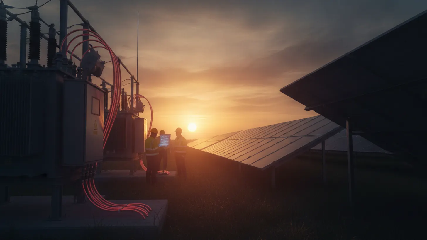
IEEE 519-2022 caps total demand distortion at 5% at the point of common coupling for systems above 161 kV, with progressively tighter tiers at lower voltage classes tied to the short-circuit ratio. That single number decides whether a utility-scale plant clears interconnection witness or restarts commissioning at owner cost. Solar farm harmonic distortion is now a pass/fail engineering deliverable, and the filter and study strategy set at the FEED stage determines cost more than any post-energization tweak.
What IEEE 519-2022 sets for solar farm harmonic distortion at the PCC
IEEE 519-2022 defines total demand distortion at the point of common coupling as the aggregate current distortion referenced to a plant maximum demand load current. At and above 161 kV, the ceiling is 5% TDD. Solar farm harmonic distortion compliance is measured at that bus, not at inverter terminals.
The 2022 revision replaced the 1992 individual harmonic order limits with a TDD-first framework tied to the short-circuit ratio. A weaker bus (low SCR) tightens the allowable TDD; a stiff bus loosens it. Below 161 kV, TDD tiers step through 4.0%, 3.0%, and 2.5% depending on voltage class and SCR band. Interconnection queues across every ISO now demand a study showing the plant, after filter design, will land under the applicable band. Reference the full text through the IEEE 519-2022 standard listing and cross-check with your regional utility interconnection guide.
For a 230 kV coupling with an SCR between 20 and 50, engineers should expect the tightest TDD tier applicable to that bus. That is not a comfortable margin once you add multiple inverter blocks with unsynchronized carriers, so the filter allocation must be sized against the aggregate spectrum from the very first FEED iteration.
Inverter topologies and switching frequencies behind solar farm harmonic distortion
Utility-scale central and string inverters use IGBT half-bridges switching at 4 to 16 kHz, per EPRI power quality research. That carrier band drives the harmonic emission spectrum on the collector system. Odd-order harmonics dominate the low band: the 5th, 7th, 11th, and 13th are the classic offenders, with a secondary cluster near the switching frequency itself.
Central inverters at 2 to 4 MVA typically switch lower, at 4 to 6 kHz, to manage IGBT thermal losses. Their emissions concentrate below 1 kHz plus a switching-band peak. Modular string inverters at 200 to 350 kVA push toward 10 to 16 kHz, giving cleaner low-order behavior but a stronger high-order footprint that couples through parasitic capacitance in medium-voltage transformers. Neither topology is inherently better for solar farm harmonic distortion compliance; the plant-level aggregation and transformer impedance shape the outcome. The EPRI research portal hosts grid-tied inverter measurement studies worth citing directly in the interconnection package.
Carrier phase-shifting across inverter blocks is one of the cheapest mitigation moves you have. Rotating the phase reference across the collector reduces coherent addition of specific orders, provided the SCADA plant controller supports it. If you are integrating a plant controller, coordinate the setpoint framework early. Our plant controller integration guide covers the interface layer.
Scoping a harmonic study for utility-scale solar interconnection
A defensible harmonic study is built on four inputs: source-side impedance envelope from the utility, aggregate inverter emissions per certified test data, transformer sequence impedances, and collector cable capacitance. Miss any one and the interconnection engineer will reject the report.
Start with the utility Thevenin equivalent at the PCC across seasonal loading; worst-case minimum SCR is what regulators care about. Request emissions data per IEC 61000-3-6 or IEEE 1547 test reports for every inverter model. Aggregate emissions using coincidence factors, not arithmetic sums; the diversity factor between blocks matters, and NERC-registered utilities will push back on any study that sums naively. See the NERC standards portal for the reliability framework and the FERC generator interconnection procedures for queue-side requirements.
Transformer impedances at multiple frequencies, not just fundamental, matter for accurate solar farm harmonic distortion modeling. Capacitive collector cables produce resonances in the 500 Hz to 2 kHz band that amplify residual inverter emissions. Model at least the 3rd through 50th harmonics. Document assumptions clearly; the study is a permanent artifact of the interconnection application. For grid-code voltage response coordination, cross-reference our IEEE 1547 voltage ride-through guide.
Filter design for solar farm harmonic distortion mitigation
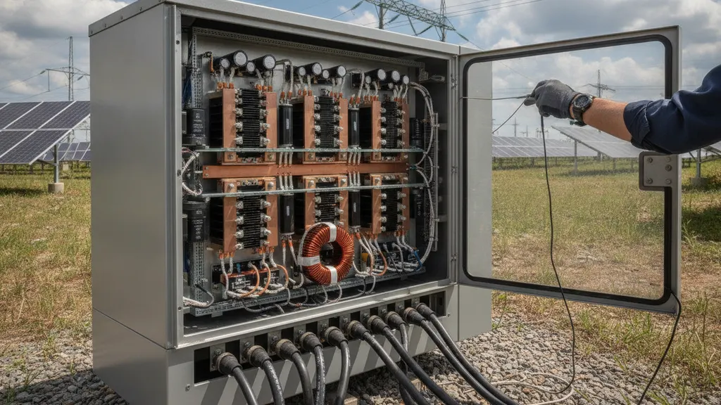
Passive shunt filters remain the workhorse for solar farm harmonic distortion attenuation at the collector bus. Tuned single-order LC branches at the 5th, 7th, and 11th orders, plus a high-pass branch above the 13th, cover most inverter aggregate spectra. Placement at the medium-voltage collector, not the HV main transformer, cuts installed cost by a meaningful margin, per EPRI power quality benchmarks.
C-type filters have a growing role at the MV bus because they present low impedance at the fundamental, reducing losses. Sizing depends on the harmonic current spectrum from the study, the capacitor MVAR budget, and the reactive power support already dispatched from the plant controller. Do not oversize the capacitor bank; you will create parallel resonance with the utility source impedance and amplify a nearby harmonic instead of attenuating it. That single failure mode drives most interconnection re-tests.
Active harmonic filters, meaning shunt inverter-based units, are appropriate where the emission profile is broadband or changes with plant output. They cost more per kVA and require control coordination with the plant controller, but they adapt as the inverter fleet ages and firmware drifts. For plants deploying batteries, active filtering may share the power conversion system. See our BESS SCADA integration guide for the control-layer overlap.
Commissioning verification and ongoing solar farm harmonic distortion reporting
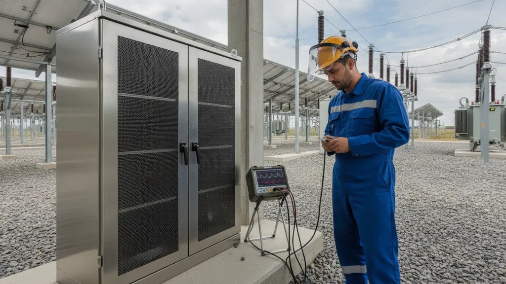
Compliance is not the study; it is measured at commissioning under IEEE 519 measurement protocols and reported to the interconnecting utility per the agreement. Class A power quality analyzers with IEC 61000-4-30 accuracy are the accepted instrument class. Measure at the PCC over a 7-day window at 10-minute averaging.
Field crews should sweep across output ranges (10%, 25%, 50%, 75%, and 100%) and repeat under partial-cloud conditions. Solar farm harmonic distortion signatures change with inverter loading; a report showing only full-output data will be rejected. Log TDD, individual harmonic distortion per order through the 50th, and voltage TDD at the PCC. Correlate against inverter output data through the SCADA historian, and archive raw waveform captures for the utility file. Our SCADA commissioning witness pack guide walks the paperwork side, and the NREL grid modernization program publishes updated field methods worth reviewing before every commissioning campaign.
Ongoing reporting varies by ISO. Most require annual power quality summaries or a re-test after any inverter firmware update that changes carrier behavior. Track firmware revisions in your asset management system and flag any release notes referencing modulation or filter changes. The US Department of Energy continues to publish sector benchmarks that help set your monitoring thresholds, and the US Energy Information Administration tracks the fleet growth driving these compliance schedules.
Frequently asked questions
What is the TDD limit under IEEE 519-2022 for a solar farm at a 230 kV PCC?
For a bus above 161 kV, IEEE 519-2022 sets a 5.0% total demand distortion ceiling in the referenced table, subject to the short-circuit ratio at the PCC. Lower voltage classes have tighter tiers stepping through 4.0%, 3.0%, and 2.5%. Utilities publish the applicable band in the interconnection facility study or system impact study document, and any weakening of source impedance during the year will pull your allowable TDD downward. Reference the IEEE 519-2022 standard listing for the current lookup table and the accompanying SCR bands used to interpret it.
Does UL 1741 SB certification cover IEEE 519 compliance at the plant level?
No. UL 1741 SB, and by reference IEEE 1547-2018, addresses inverter-level performance including individual harmonic order limits at the inverter output terminals. IEEE 519 governs aggregate distortion at the utility PCC after transformer impedance, cable resonance, and coincidence effects apply. A certified inverter fleet can still fail solar farm harmonic distortion compliance at the PCC. Plant-level filter design and a formal harmonic study are separate deliverables, not derivable from inverter test reports alone. The EPRI power quality research library documents the aggregation gap between inverter certification and PCC compliance.
How long does a harmonic study take for a 100 MW solar interconnection?
Typical timelines run 8 to 14 weeks from utility data receipt to signed report. The gating item is the utility Thevenin impedance envelope and any frequency scans they can share. Modeling and aggregation take 3 to 4 weeks; iteration with filter design adds another 3 to 4 weeks. Interconnection review and comment loops finish the sequence. If you are stacked into an ISO queue milestone, front-load the utility data request weeks before the deliverable is due. The FERC pro-forma large generator interconnection procedure outlines the parallel study track.
When is an active filter preferred over a passive filter on a solar collector system?
Active filtering earns its cost premium when the harmonic emission spectrum is broadband, when inverter dispatch changes materially through the day, or when the plant adds a battery and can share the power conversion system. Passive tuned filters remain more economical for stable spectra dominated by 5th, 7th, and 11th orders. A hybrid approach, passive branches for low orders plus a smaller active unit for residual broadband content, is common on plants above 200 MW. The US EIA tracks solar deployment scale driving many of these design decisions.
Which harmonic orders cause the most trouble on utility-scale solar plants?
The 5th, 7th, 11th, and 13th orders dominate the low-order spectrum from IGBT inverters. Above that, a switching-frequency cluster near 4 to 16 kHz produces problems when collector cable capacitance resonates in the 500 Hz to 2 kHz range. Even orders and triplens are usually low if inverter DC-side balance is maintained. Design your study to model at least through the 50th order; skipping the mid-band region is where most compliance failures originate. The NREL grid integration program publishes measurement data that supports these bands and their filter design implications.
Do you have to retest for IEEE 519 compliance after a repower or expansion?
Yes, in nearly every jurisdiction. Adding inverter capacity changes plant demand load current, which shifts the TDD reference. Repowering with new inverter models introduces different switching frequencies and emission profiles. Utilities require an updated study and, in most cases, a repeat 7-day measurement window at the PCC after commissioning. Track this as a hard gate in your project schedule so it does not slip beyond the utility witness date. The NERC reliability standards library outlines the reporting expectations for registered entities managing multi-phase solar builds.